Operating conditions
Recommended operating conditions. Stay inside these for rated performance. Absolute limits are in the ratings section.
| Parameter | Min | Typ | Max | Unit | Note |
|---|---|---|---|---|---|
| Servo supply voltage | 6 | 12 | 12.6 | V | ST3215 supply range. A 3S lithium pack (9.0 to 12.6 V) or a 12 V supply. |
| Current per port, continuous | 0.2 | 2.7 | A | 0.2 A: an ST3215 holding position. 2.7 A: ST3215 stall at 12 V. The PTC holds 3 A at 25 °C but only 2.5 A at 40 °C. | |
| Total current, continuous | 16 | A | 80 % of the 20 A fuse. | ||
| 3V3 from a programmer (logic only, no 12 V) | 3.2 | 3.3 | 3.4 | V | Into the 3V3 pin of J14 or J15. |
| Logic supply current | 45 | mA | Estimate: STM32 at 72 MHz, LEDs, regulators. Drawn from 12 V through the 78L05, or from a programmer's 3V3. | ||
| Kookabus or I²C header 3V3 from the host | 3.0 | 3.3 | 3.6 | V | Pull-ups only; under 1 mA. |
| I²C bus speed | 400 | 400 | kHz | STM32F103 fast mode. The board does not stretch the clock. | |
| Servo bus speed | 1 | 1 | Mbps | ST3215 default. Other rates TBD in firmware. | |
| Operating ambient temperature | 0 | 25 | 40 | °C | For the full 2.7 A per port. Above 40 °C a stalled servo can trip its PTC. |
How the power is distributed
Servo power runs on the top copper from the XT60, through the reverse-polarity stage and the fuse to a central hub, and out to the eight ports on eight equal spokes. Each spoke has its own 3 A resettable fuse, so one stalled or shorted servo trips only its own port. The bottom layer is a ground plane.
The 5 V rail feeds the 3.3 V regulator and the servo side of the bus translator. With no 12 V, an ST-Link on J15 or a USB-serial adapter on J14 can power the logic through its 3V3 pin; the servo ports are then unpowered, so the board can be flashed and configured but cannot move servos.
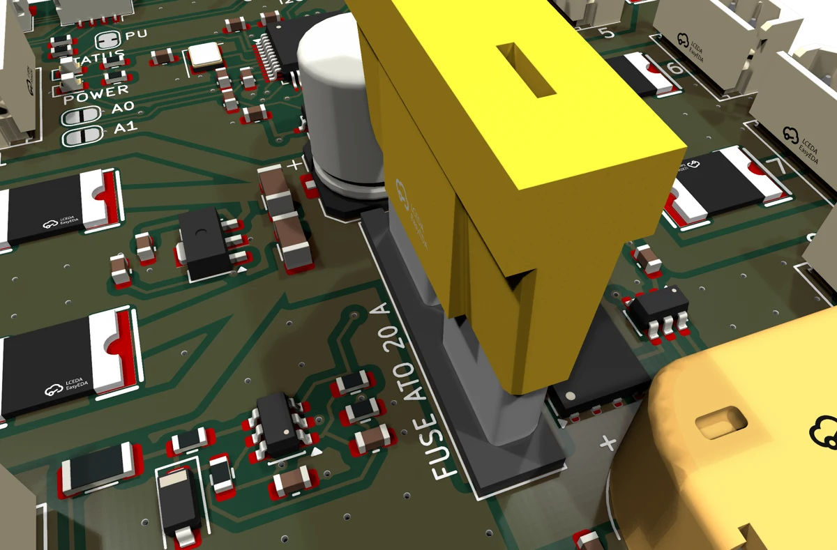
Never connect a programmer's 3V3 while 12 V is connected. Both would drive the 3.3 V rail.
Ratings
Absolute maximum ratings
Stresses beyond these values may cause permanent damage. These are limits, not operating conditions.
| Parameter | Min | Max | Unit | Limiting part or note |
|---|---|---|---|---|
| 12 V input voltage (XT60) to GND | -30 | 15 | V | Positive: SMBJ15A standoff. The TVS starts to conduct at 16.7 V and a sustained overvoltage blows the 20 A fuse. Negative: a reversed supply is blocked by the ideal-diode FET (30 V VDS). |
| Transient on the hub (clamped) | 24.4 | V | TVS clamp at its rated 24.6 A surge. This equals the PTCs' 24 V maximum. | |
| Total input current, continuous | 20 | A | Fuse rating. | |
| Current per servo port | 40 | A | PTC maximum fault current. The PTC trips well before this. | |
| DATA pin of a servo port to GND | -0.5 | 12.6 | V | Clamped by the 5.6 V zener through 180 Ω, indefinitely. Negative voltage is not protected: R7 would exceed its 0.25 W rating. |
| SDA, SCL, UART RX to GND | -0.3 | 5.5 | V | STM32 5 V tolerant pins; PESD5V0S2BT on SDA and SCL. |
| 3V3 pin of a Kookabus connector or the I²C header to GND | -0.3 | 5.5 | V | Feeds only the I²C pull-ups; PESD5V0S2BT clamps above 5 V. |
| ESD on SDA, SCL (IEC 61000-4-2, contact) | 8 | kV | PESD5V0S2BT. | |
| Operating ambient temperature | -20 | 70 | °C | Limited by the electrolytic capacitor, connectors and PTC derating. Not characterised over temperature. |
| Storage temperature | -40 | 85 | °C |
Electrical characteristics
Calculated at 25 °C from component datasheets unless stated. VIN is the XT60 input; V12 is the hub after the ideal diode and fuse; SERVO_Vn is port n's V+ pin after its PTC.
Power path
| Parameter | Condition | Min | Typ | Max | Unit |
|---|---|---|---|---|---|
| Ideal-diode FET on-resistance | BRCS016N03ZC | 2 | mΩ | ||
| FET dissipation | 8 A (eight servos moving) / 20 A | 0.13 / 0.8 | W | ||
| Reverse current, V12 back into the input | Input removed or reversed | 0 | A | ||
| Hub capacitance | 470 µF electrolytic plus 2 × 10 µF ceramic | 490 | µF | ||
| PTC hold current | Never trips at or below, 25 °C still air | 3.0 | A | ||
| PTC trip current | Always trips at or above, 25 °C | 5.0 | A | ||
| PTC time to trip | 8 A | 20 | s | ||
| PTC resistance | New / after a trip or reflow | 12 | 48 | mΩ | |
| Port voltage drop, hub to V+ pin | 2.7 A; PTC plus 2.4 to 6.7 mΩ of copper | 39 | 148 | mV | |
| Copper difference between ports | Inner ports 2, 3, 6, 7 against outer ports | 4 | mΩ | ||
| PTC dissipation when tripped | Surface up to 125 °C | 2 | W |
Logic power
| Parameter | Condition | Min | Typ | Max | Unit |
|---|---|---|---|---|---|
| 5 V rail (78L05) | From V12, 30 V input rating | 4.75 | 5.0 | 5.25 | V |
| 5 V rail load capacity | 100 | mA | |||
| 78L05 dissipation | 12 V in, 45 mA | 0.32 | W | ||
| 3.3 V rail (XC6206) | From the 5 V rail | 3.23 | 3.3 | 3.37 | V |
| POWER LED (yellow) | On whenever 3.3 V is present, 1 kΩ | 1.3 | mA | ||
| STATUS LED (red) | PC13 low, 1 kΩ from 3.3 V | 1.4 | mA |
Servo bus
| Parameter | Condition | Typ | Unit |
|---|---|---|---|
| Bus logic level | SN74LVC1T45 B side at 5 V, 10 kΩ pull-up to 5 V | 5 | V |
| Series resistance to DATA | 47 Ω, zener node, 180 Ω 1206 | 227 | Ω |
| Edge time constant | 400 pF of servo cabling | 90 | ns |
| DATA shorted to 12.6 V | Clamp voltage / current / R7 dissipation | 6 / 35 / 0.23 | V / mA / W |
| Direction during reset | PA4 pulled low by 10 kΩ: receive |
Supply monitor
| Parameter | Condition | Typ | Unit |
|---|---|---|---|
| Divider | 100 kΩ / 10 kΩ, 1 %, 100 nF filter, V12 to PB1 (ADC1_IN9) | 1 : 11 | |
| Full scale / resolution | 12-bit ADC, 3.3 V reference | 36.3 / 8.9 | V / mV |
| Accuracy | Divider tolerance plus the 3.3 V regulator's 2 % | ±3 | % |
| Divider current from V12 | 12 V | 0.11 | mA |
Connectors and jumpers
Power input
| Ref | Silkscreen | Part | Rating | Note |
|---|---|---|---|---|
| J1 | 12 V IN | Amass XT60PW-M (male, PCB, right-angle) | 30 A | Mates with a female XT60 pack or supply lead. |
Servo ports
| Ref | Port | Part | Pin 1 | Pin 2 | Pin 3 |
|---|---|---|---|---|---|
| J4 to J11 | 1 to 8 | CJT A2501WV-3P, 2.5 mm, vertical (Molex 5264 compatible) | GND | V+ (SERVO_Vn) | DATA |
All eight DATA pins are one bus: every servo needs a unique ID. Ports 1 to 4 are on the left edge and 5 to 8 on the right, numbered on the silkscreen. The latch side of each header faces the board edge, so plugs can be gripped and released.
Draft: the pin order is from Feetech-based sources and is still to be confirmed against a real ST3215 lead before the board is ordered.
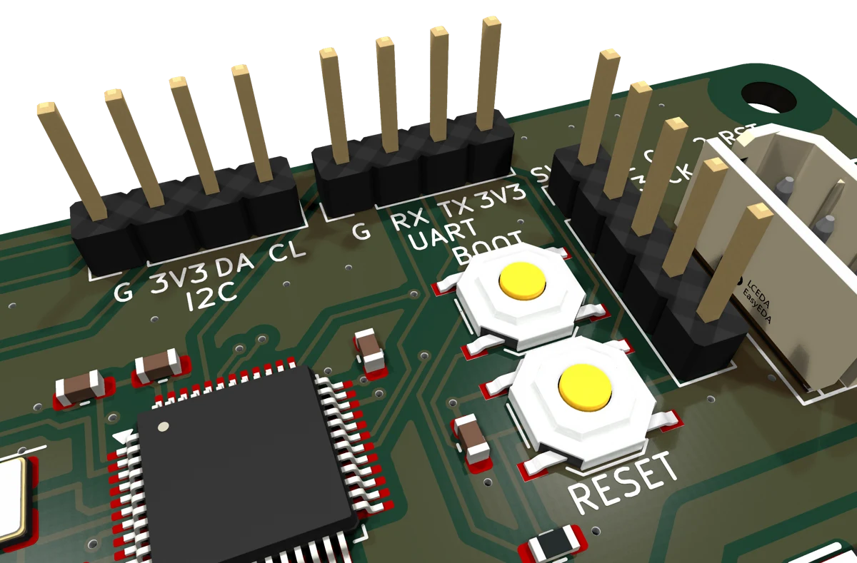
Control connectors
| Ref | Label | Part | Pin 1 | Pin 2 | Pin 3 | Pin 4 | Pin 5 |
|---|---|---|---|---|---|---|---|
| J12, J13 | Kookabus | JST SH 1.0 mm 4-way horizontal | GND | 3V3 (pull-ups only) | SDA | SCL | |
| J2 | I2C | 2.54 mm 1 × 4 header | GND | 3V3 (pull-ups only) | SDA | SCL | |
| J14 | UART | 2.54 mm 1 × 4 header | GND | RX (in) | TX (out) | 3V3 | |
| J15 | SWD | 2.54 mm 1 × 5 header | GND | NRST | SWCLK | SWDIO | 3V3 |
J12 and J13 are wired in parallel for daisy-chaining and use the Qwiic and PiicoDev pin order. J2 is the same bus on a pin header, in the same pin order, for jumper wires when no Qwiic cable is at hand. Unlike Kookabus-01, the board does not draw power from the Kookabus 3V3 pin; it only feeds the I²C pull-ups (through JP3). The UART header's RX input is 5 V tolerant; TX drives 3.3 V.
Buttons and jumpers
| Ref | Silkscreen | Function | As supplied |
|---|---|---|---|
| SW1 | RESET | Resets the microcontroller. | |
| SW2 | BOOT | Holds BOOT0 high. Hold BOOT, tap RESET, release BOOT to enter the ROM serial bootloader on J14. | |
| JP1 | A0 | Address bit A0 (PA0). Bridged adds 1 to the address. | Open |
| JP2 | A1 | Address bit A1 (PA1). Bridged adds 2 to the address. | Open |
| JP3 | PU | Connects the 4.7 kΩ SDA and SCL pull-ups to the host's 3V3. Cut to remove them when the host or another board already provides them. | Bridged (pull-ups on) |
Fuses
F1 is an ATO/ATC blade fuse holder rated 30 A. Fit a 20 A, 32 V ATO blade fuse (Littelfuse 0287020.PXCN or equivalent). The fuse ships separately and must be fitted before use. F2 to F9 are BHFUSE BSMD2920-300-24V resettable PTCs, one per port, soldered in place. A tripped PTC resets by itself once the fault is removed and it has cooled.
Control interface
Draft: the firmware and its register map are not yet written. This section lists what the hardware provides and what the firmware is planned to do. Registers and commands are TBD.
Planned functions
- Read position, speed, load, voltage and temperature from each servo.
- Write target position, speed and acceleration, singly or to several servos at once.
- Scan the bus for servos, and assign servo IDs without a separate programmer.
- Read the 12 V supply voltage.
- The same command set over I²C and the UART header.
I²C address
JP1 and JP2 select one of four addresses, so up to four Kookabus-02 boards can share one I²C bus. The addresses are clear of Kookabus-01 (0x40 to 0x45) and common Qwiic and PiicoDev devices. The table is also printed on the back of the board.
| JP2 (A1) | JP1 (A0) | Address (7-bit) |
|---|---|---|
| Open | Open | 0x14 (as supplied) |
| Open | Bridged | 0x15 |
| Bridged | Open | 0x16 |
| Bridged | Bridged | 0x17 |
Microcontroller pin use
| Pin | Port | Function |
|---|---|---|
| 2 | PC13 | STATUS LED, active low |
| 5, 6 | PD0, PD1 | 8 MHz crystal |
| 10, 11 | PA0, PA1 | Address jumpers A0, A1 (internal pull-ups; bridged reads low) |
| 12 | PA2 | USART2 TX, single-wire half-duplex servo bus (10 kΩ pull-up) |
| 14 | PA4 | Servo bus direction: high = transmit (10 kΩ pull-down) |
| 19 | PB1 | ADC1_IN9, V12 sense |
| 20 | PB2 | BOOT1, 10 kΩ to GND |
| 30, 31 | PA9, PA10 | USART1 TX, RX to J14; ROM bootloader |
| 34, 37 | PA13, PA14 | SWDIO, SWCLK |
| 42, 43 | PB6, PB7 | I2C1 SCL, SDA (Kookabus J12, J13 and header J2) |
| 44 | BOOT0 | BOOT button, 10 kΩ to GND |
Flashing with an ST-Link or a USB-serial adapter is covered on the code page.
Schematic
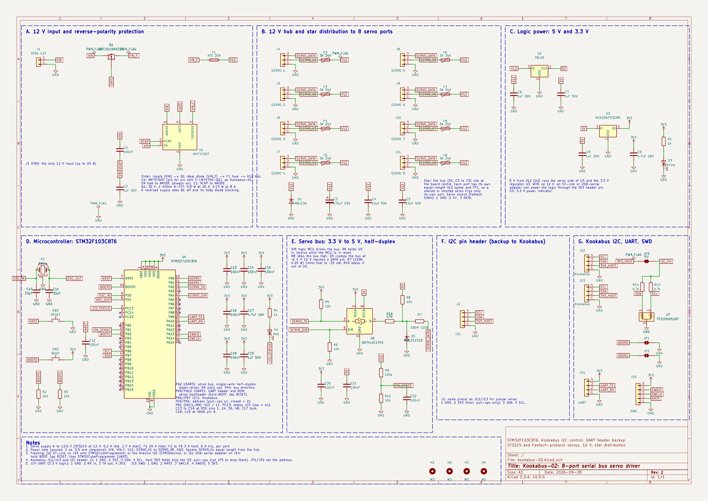
Sheet sections: the 12 V input with reverse-polarity protection (MX74700T and BRCS016N03ZC), the 12 V hub with its fuse, TVS and star distribution to the eight servo ports, the 5 V and 3.3 V logic regulators, the STM32F103 microcontroller, the half-duplex servo bus translator with its 12 V fault clamp, and the I²C connectors with ESD protection and pull-up jumper.
Protection and safety
| Event | Response |
|---|---|
| Supply connected reversed | Blocked by the ideal diode. No current flows and nothing is damaged (up to -30 V). |
| Short on one servo port, or a servo stalled above 3 A | That port's PTC trips and limits the port to a trickle. The other seven ports keep running. The PTC resets once the fault is removed and it cools. |
| Servo stalled at 2.7 A | Below the PTC hold current at 25 °C, so the port stays on; the servo's own overload protection must act. In a warm enclosure (40 °C and above) the PTC may trip instead. |
| 12 V applied to a DATA pin (for example a miswired lead) | Clamped to about 6 V through 180 Ω, indefinitely. The servo bus stops working during the fault; nothing is damaged. |
| Voltage transient on the supply | Clamped by the SMBJ15A on the hub. A sustained overvoltage above about 17 V blows the 20 A fuse. |
| Short on the hub, or several ports faulted at once | The 20 A blade fuse opens. Replace it with the same rating. |
| A programmer's 3V3 and 12 V connected together | Not protected: the programmer and the on-board regulator both drive the 3.3 V rail. Connect the 3V3 pin only when 12 V is off. |
| Battery over-discharge | Not protected on the board. Read the supply voltage over I²C and stop the servos at the pack's minimum, or use a pack with its own cut-off. |
Warning. Lithium packs and bench supplies can deliver hundreds of amps into a short circuit. Fit the 20 A fuse before connecting power, and keep loose metal away from the servo headers. Do not supply more than 12.6 V: the PTCs are rated 24 V and the TVS clamps at 24.4 V, so there is little margin above the servos' own limit. A tripped PTC runs at up to 125 °C; do not touch it.
Mechanical
| Board size | 75.0 × 75.0 mm, 3 mm corner radius |
|---|---|
| Thickness | 1.6 mm FR-4, 2 layers, 2 oz copper both sides |
| Finish | Lead-free HASL, green solder mask, white silkscreen |
| Mounting holes | 4 × 3.2 mm for M3, centres 3.5 mm from each edge (68.0 × 68.0 mm pattern), 3.6 mm radius clear of copper for screw heads |
| Component height, top | About 20 mm at the ATO fuse, 10.5 mm at the electrolytic capacitor, 8.5 mm at the XT60 (to be measured) |
| Component height, bottom | None. Through-hole leads protrude up to 1.5 mm. |
| Connector overhang | XT60: about 0.5 mm past the bottom edge. |
| Mass | TBD |
Connector positions
Board-local coordinates, origin at the top-left corner of the outline as viewed from the top, x to the right, y down.
| Ref | x (mm) | y (mm) | Note |
|---|---|---|---|
| J4 to J7, ports 1 to 4 (pin 2) | 12.76, 6.68, 6.68, 12.76 | 16.5, 29.5, 42.5, 55.5 | Pins on 2.5 mm pitch along y; 13 mm between ports |
| J8 to J11, ports 5 to 8 (pin 2) | 62.24, 68.32, 68.32, 62.24 | 16.5, 29.5, 42.5, 55.5 | Mirror image of ports 1 to 4 |
| J1 XT60 | 52.0 | 59.15 | Pins on 7.2 mm pitch along x; face at the bottom edge |
| J12, J13 Kookabus | 11.9, 20.5 | 3.4 | Opening at the top edge |
| J2 I²C header (pin 1) | 33.8 | 3.3 | Pins on 2.54 mm pitch along x |
| J14 UART (pin 1) | 45.2 | 3.3 | Pins on 2.54 mm pitch along x |
| J15 SWD (pin 1) | 56.5 | 7.5 | Pins on 2.54 mm pitch along y |
| SW2 BOOT, SW1 RESET | 50.8 | 12.6, 18.4 | |
| F1 fuse | 37.5 | 47.5 | Blade slots along y |
| H1 to H4 holes | 3.5, 71.5 | 3.5, 71.5 | 3.2 mm |
Application notes
Typical connection
- Fit a 20 A ATO fuse in F1.
- Give every servo a unique ID first. Out of the box, ST3215 servos all use ID 1, so connect them one at a time for this step.
- Plug the servos into any ports.
- Connect the host's Qwiic or PiicoDev port to J12 or J13 (or jumper wires to the J2 header). Use the other connector to chain further I²C boards.
- Connect 12 V to the XT60. The POWER LED lights.
Sizing the supply
An ST3215 draws about 0.2 A holding position and up to 2.7 A stalled at 12 V. Size the supply for the servos that move together and are heavily loaded, not for eight stalls: eight servos moving under moderate load draw about 8 A.
Thermal
At 8 A the ideal-diode FET dissipates about 0.13 W and each moving port's PTC under 0.1 W. The 78L05 dissipates about 0.3 W from 12 V. No heatsink is needed. The PTCs' hold current falls as they warm (2.5 A at 40 °C, 2.3 A at 50 °C), so in a closed enclosure a servo held near stall for a long time can trip its port. Ventilate the enclosure, or keep sustained loads below the derated hold current.
Revisions
| Board rev | Date | Change |
|---|---|---|
| 1 | 28 September 2026 | First design: eight ports, STM32F103 with native USB, three parallel 12 V inputs. The MCU area was re-laid out after review: crystal beside the MCU, decoupling capacitors on their pins, shorter reset line. |
| 2 | 28 September 2026 | Cost-down: USB-C removed (with its ESD chip, CC and pull-up resistors and the BAT54C OR diode); XT60 is the only 12 V input (screw terminal and barrel jack removed); new 2.54 mm I²C pin header J2; address jumpers moved to PA0/PA1, addresses set to 0x14 to 0x17; website address on the front and the address table and Adventures in Silicon logo on the back. |
| Document rev | Date | Change |
|---|---|---|
| 0.1 | 28 September 2026 | First draft, for board revision 1. Calculated values only; firmware interface to be defined. |
| 0.2 | 28 September 2026 | Updated for board revision 2. I²C addresses defined. |
Information on this page is believed to be accurate at the date of publication but is provided without warranty. Values marked as calculated have not been verified by measurement. Adventures in Silicon Pty Ltd accepts no liability for damage or injury arising from the use of this product, which connects to supplies and batteries capable of high fault currents. The user is responsible for fusing, supply protection, enclosure and compliance with local regulations. Product names are trademarks of their respective owners.