Getting started
- Fit a 20 A ATO fuse in F1. It ships separately.
- Give every servo a unique ID first. Out of the box, ST3215 servos all use ID 1, so connect them one at a time for this step.
- Plug the servos into any ports. All eight ports are one bus, so any servo can go in any port.
- Connect the host's Qwiic or PiicoDev port to J12 or J13 with a 4-way JST SH cable, or jumper wires to the J2 header. Use the other connector to chain further I²C boards. The board ships with pull-ups on; cut JP3 if the host or another board already has them.
- Connect 12 V to the XT60. The POWER LED lights.
Firmware and host examples
Not yet written. The firmware, its register map and the host examples will be published here before the board ships. Until then, this page lists what the firmware is planned to do.
- Read position, speed, load, voltage and temperature from each servo.
- Write target position, speed and acceleration, singly or to several servos at once.
- Scan the bus for servos, and assign servo IDs without a separate programmer.
- Supply voltage: read the 12 V hub, so the host can stop the servos at a pack's minimum.
- Two interfaces: the same command set over I²C (up to 400 kHz, no clock stretching) and the 3.3 V UART header.
The I²C address is set by jumpers A0 and A1: 0x14 as supplied, up to 0x17. The full table and the microcontroller pin map are in the control interface section of the specifications.
Flashing the microcontroller
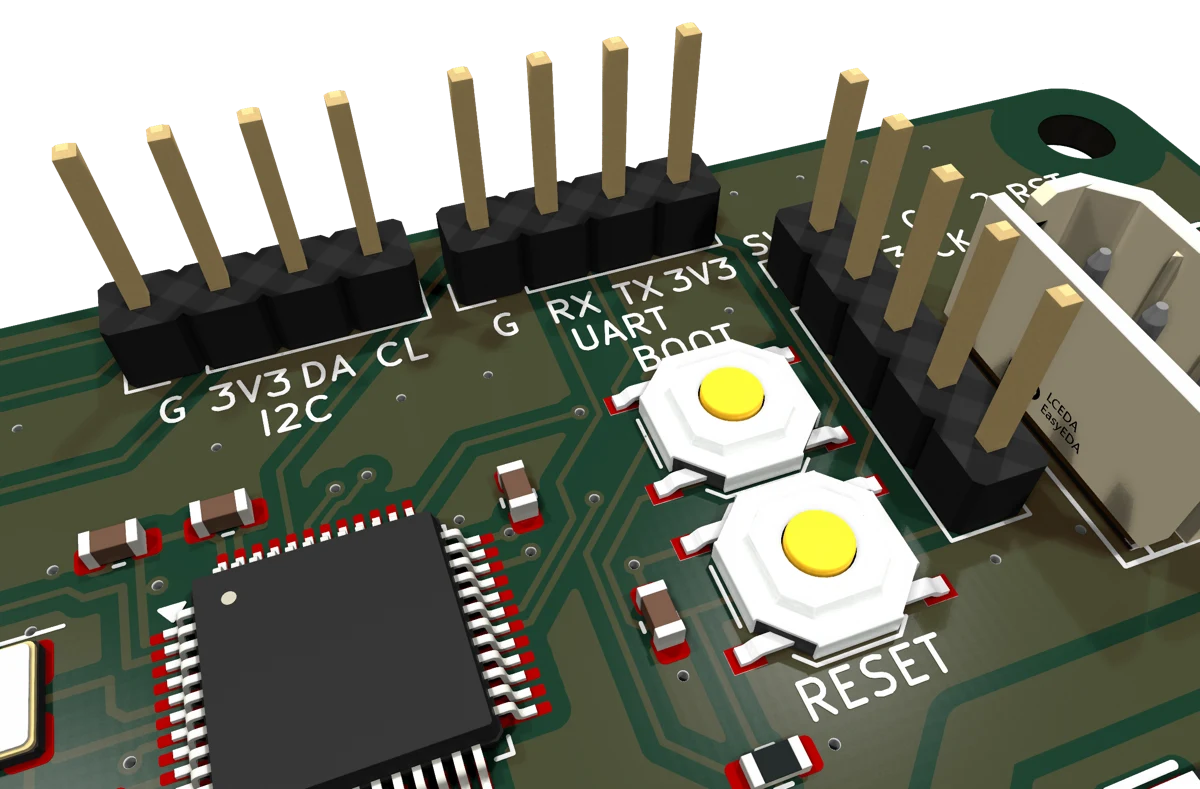
The board uses an STM32F103C8T6 and has no USB port, so firmware is loaded in one of two ways. Use method 1 for the first flash.
The board needs power while you flash it: 12 V on the XT60, or 3.3 V from the ST-Link or USB-serial adapter through the header's 3V3 pin. Use one or the other, never both.
Method 1: ST-Link on the SWD header (recommended)
This works every time, even on a blank chip. You need an ST-Link V2 USB dongle (about AUD $10; the official STLINK-V3MINIE also works), four female-to-female jumper wires, and STM32CubeProgrammer (free from st.com, for Windows, macOS and Linux).
| J15 pin | Board | ST-Link pin |
|---|---|---|
| 1 | GND | GND |
| 2 | NRST | RST (optional) |
| 3 | SWCLK | SWCLK |
| 4 | SWDIO | SWDIO |
| 5 | 3V3 | 3V3, to power the board from the ST-Link. Leave unconnected when 12 V is connected. |
- Connect the dongle to J15 as in the table.
- Power the board: either connect pin 5 to the ST-Link's 3V3, or plug in 12 V and leave pin 5 unconnected.
- In STM32CubeProgrammer choose ST-LINK, click Connect, open the
.hexor.binfile, and click Download.
Arduino IDE alternative: install the STM32duino core (Boards Manager: "STM32 MCU based boards"), pick "Generic STM32F1 series", board part "BluePill F103C8", and set Upload method to "STM32CubeProgrammer (SWD)". The Upload button then flashes through the ST-Link.
Method 2: USB-serial adapter on the UART header
The chip has a serial bootloader built in, so no ST-Link is needed. You need a 3.3 V USB-serial adapter (CP2102, CH340 or FTDI).
- Connect to J14 (UART): adapter GND to pin 1, adapter TX to pin 2 (RX), adapter RX to pin 3 (TX). Connect pin 4 to the adapter's 3V3 only if 12 V is not connected.
- Hold BOOT, tap RESET, release BOOT. The chip is now in its bootloader.
- In STM32CubeProgrammer choose UART, pick the adapter's port, click Connect, then Download.
- Tap RESET to run the new firmware.