The problem it solves
Serial bus servos such as the ST3215 are awkward to connect. They talk on a 1 Mbps half-duplex serial line that ties up a UART and needs extra circuitry on the controller. They are also usually daisy-chained on one power lead, so a single stalled or shorted servo can pull the whole chain down.
Kookabus-02 puts eight servo ports behind the I²C connector your controller already has. An on-board microcontroller runs the servo bus, and every port has its own resettable fuse, so a faulty servo trips only its own port.
- Servos
- 8 ports on one shared busST3215 and Feetech STS, SMS and SCS bus servos
- Supply
- 6 to 12.6 V on XT6012 V nominal, 16 A continuous total
- Per port
- 2.7 A, own 3 A resettable fuseA shorted servo trips only its own port
- Protection
- Reverse polarity, 20 A ATO fuseTVS on the hub, DATA survives a 12 V short
- Control
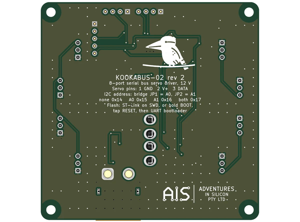
- I²C 0x14 to 0x17, or 3.3 V UARTQwiic and PiicoDev, plus a 2.54 mm header
- MCU
- STM32F103, 1 Mbps servo busSWD header and ROM serial bootloader
- Size
- 75 × 75 mm, four M3 holesPrintable enclosure with DIN-rail clip
- Status
- Rev 2, in developmentComing 1 November 2026
What it does
Kookabus-02 drives up to eight Feetech-protocol serial bus servos, such as the ST3215, from a Kookabus, Qwiic or PiicoDev I²C host. An STM32F103 runs the servos' 1 Mbps half-duplex bus, so your controller reads and writes servos with ordinary I²C transactions. The same commands are available over a 3.3 V UART header, and a 2.54 mm I²C pin header backs up the Kookabus connectors for jumper wires.
A single 12 V supply feeds a central hub through ideal-diode reverse-polarity protection and a 20 A blade fuse. Each port takes its power straight from the hub through its own 3 A resettable fuse, so one stalled or shorted servo trips only its own port and the other seven keep running.
- Robot arms, legs and pan-tilt heads built from ST3215, STS, SMS or SCS bus servos.
- Adding bus servos to a ROS 2, Raspberry Pi, Jetson or microcontroller robot that already uses Qwiic or PiicoDev sensors.
- Bench set-up of servo IDs and limits from a PC through a USB-serial adapter on the UART header.
Find what you need
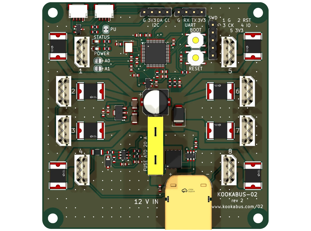
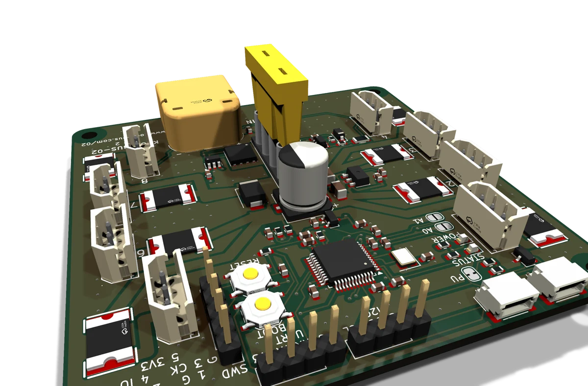
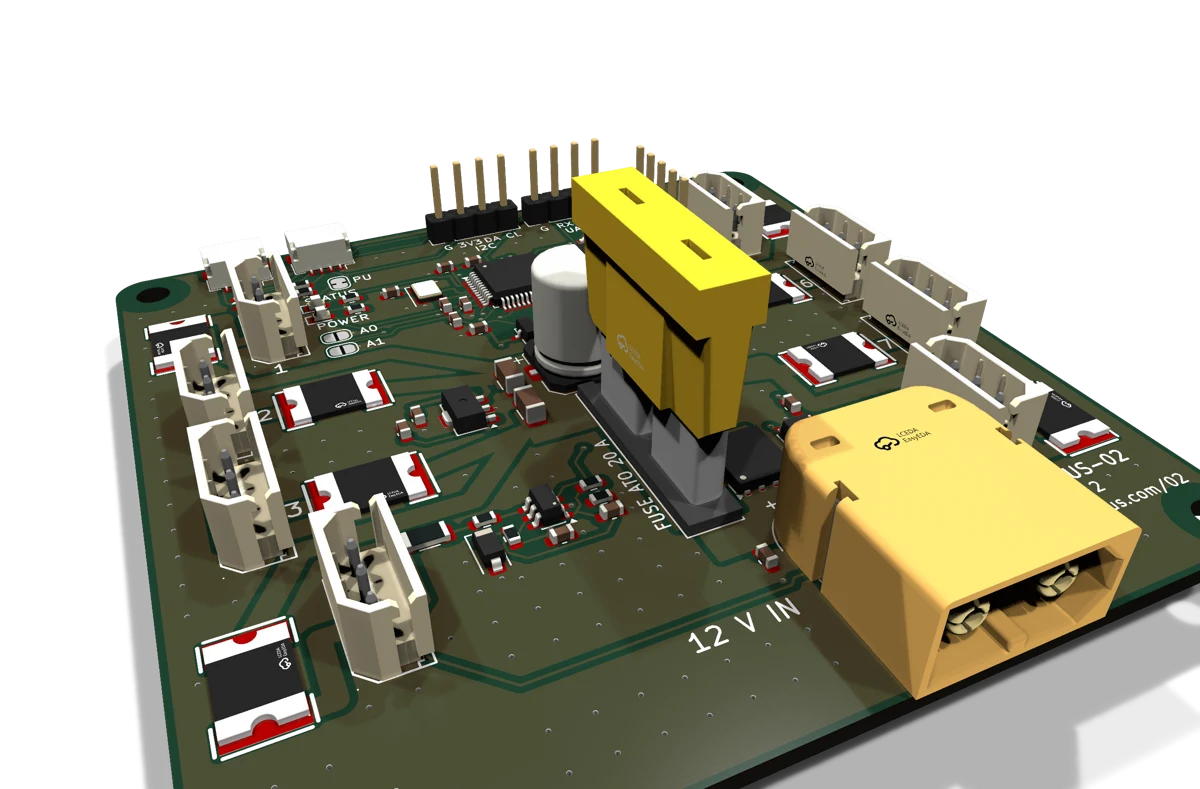
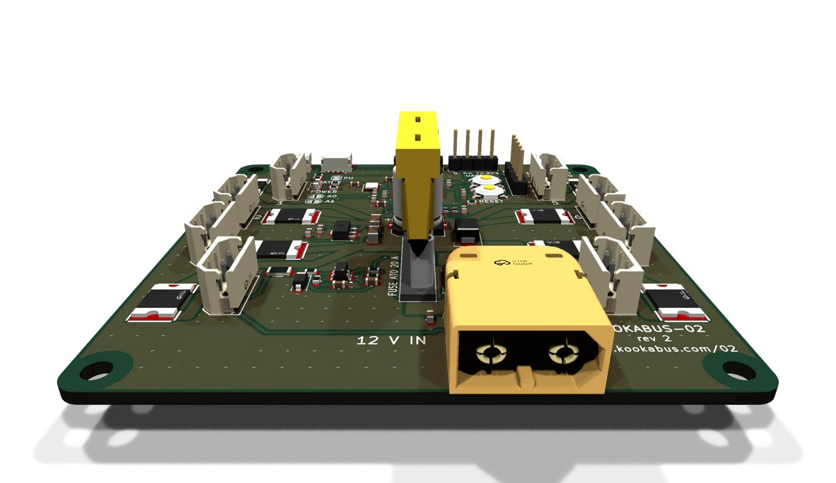
The board
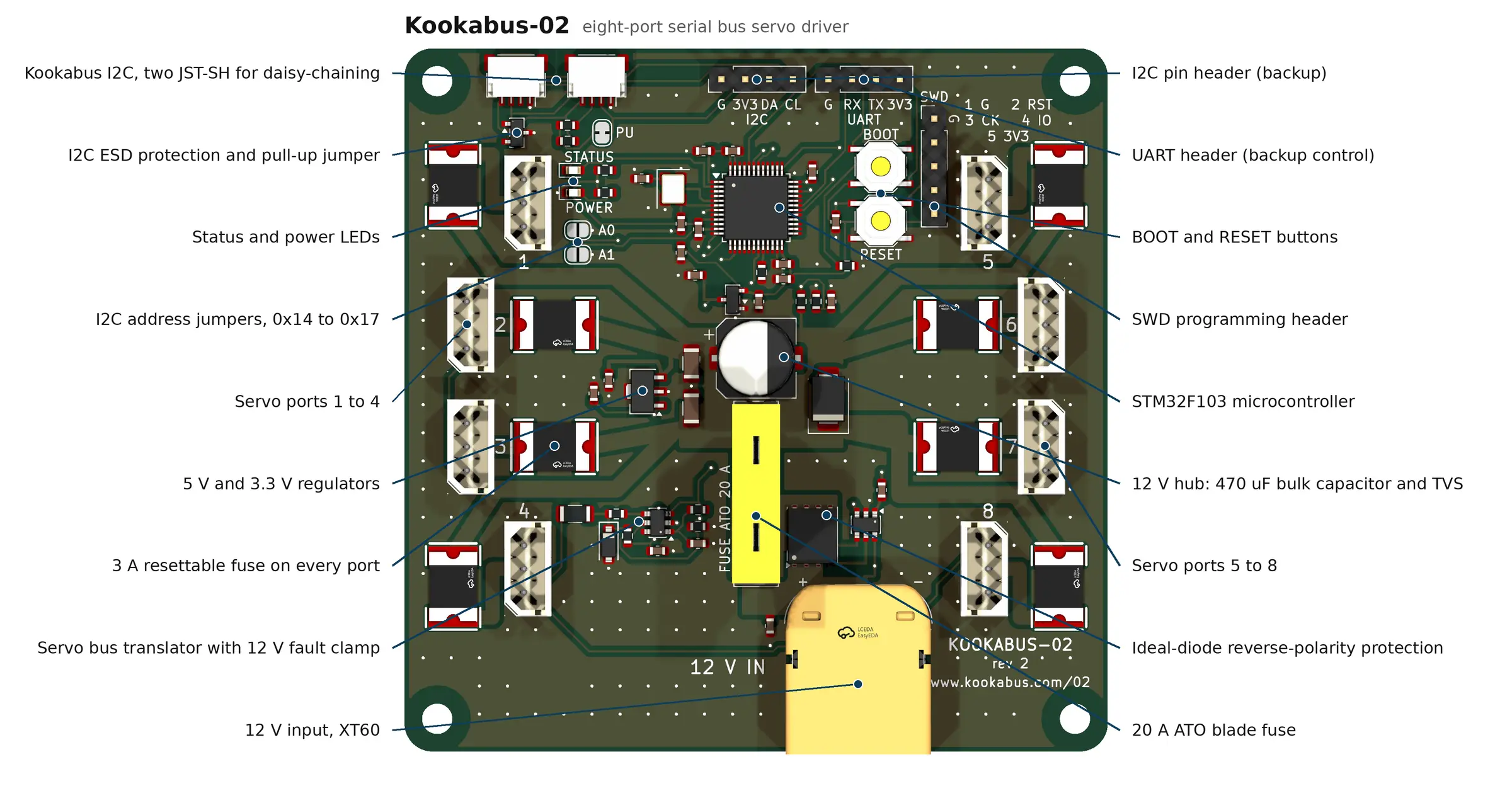
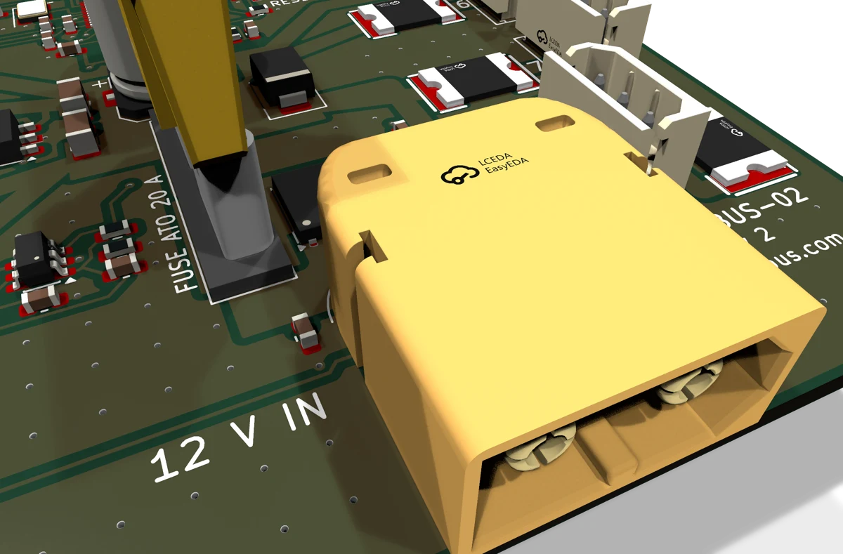
- J1
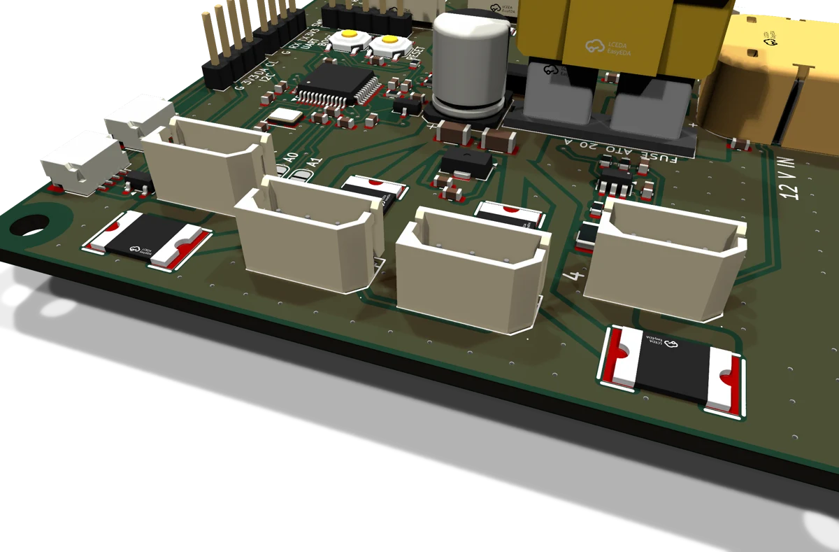
- 12 V IN. Male XT60, face 0.5 mm past the bottom edge.
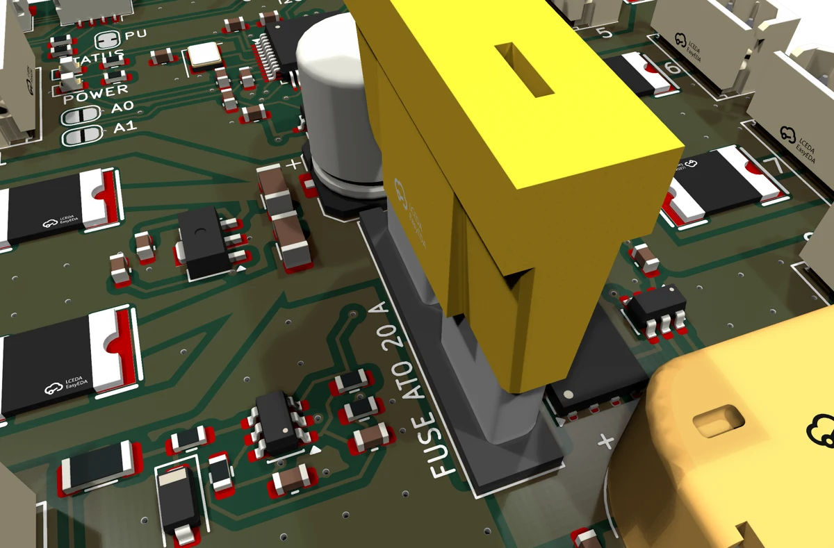
- F1
- ATO blade fuse holder. Fit a 20 A fuse before use.
- F2 to F9
- 3 A resettable PTC fuse for each port.
- J4 to J11
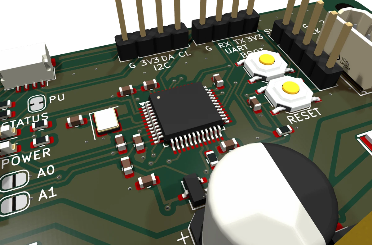
- Servo ports 1 to 8. 2.5 mm 3-pin headers, ports 1 to 4 on the left, 5 to 8 on the right.
- J12, J13
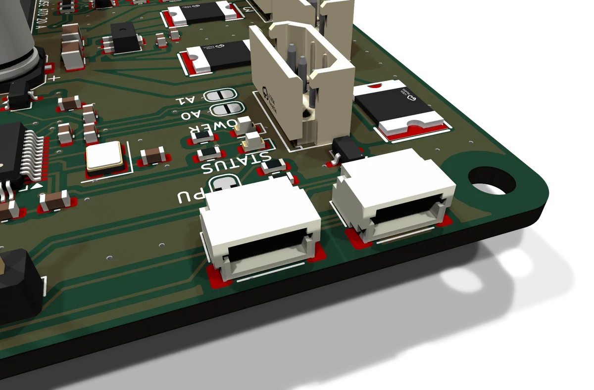
- Kookabus JST-SH 4-way I²C connectors, wired in parallel.
- J2
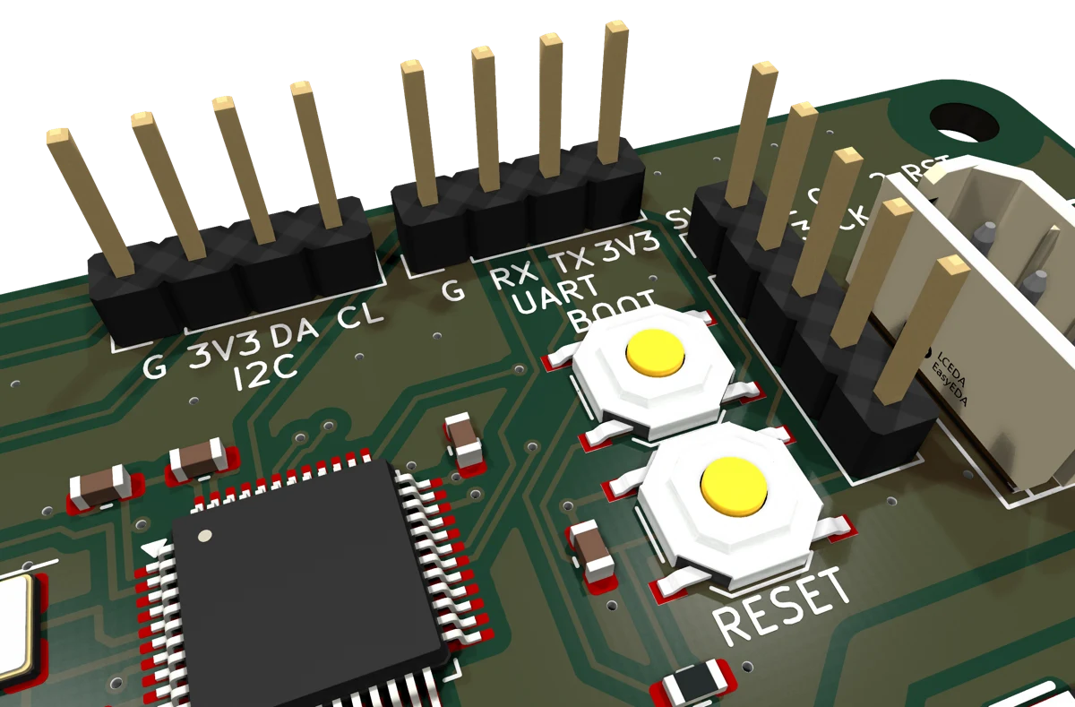
- I²C on a 2.54 mm pin header, same bus and pin order.
- J14
- UART header: GND, RX, TX, 3V3. Backup control and the ROM bootloader.
- J15
- SWD programming header.
- SW1, SW2
- RESET and BOOT buttons.
- A0, A1
- JP1 and JP2, I²C address jumpers.
- PU
- JP3, cut to remove the 4.7 kΩ pull-ups.
- POWER, STATUS
- Yellow LED on whenever 3.3 V is present; red LED under firmware control.
More views