

The problem it solves
Small robots and servo projects need 6 to 12 V. The usual answers are a lithium pack, which needs a charger and careful handling, or a bare AA holder with loose wires, no fuse and no way to tell whether the cells are flat.
Kookabus-03 turns AA cells from any shop into a proper supply. A switch picks 4, 6 or 8 cells, a 3 A resettable fuse covers shorts, the output is an XT60, and a TEST button shows green for good cells and red for flat ones.
- Cells
- Up to 8 × AA, alkaline or NiMHOne 4 × AA and two 2 × AA holders, wired to the board
- Output
- 4, 6 or 8 cells in series6 / 9 / 12 V alkaline, 4.8 / 7.2 / 9.6 V NiMH
- Current
- 3 A, resettable fuse3 A hold, 5 A trip
- Connector
- XT60, femaleReverse current blocked: a supply or charger on the XT60 cannot charge the cells
- Battery check
- TEST button, green and red LEDsHold TEST: green OK, red flat, for the cells in use
- Idle drain
- Up to 13 µAAbout 4.5 % of an alkaline AA a year. No off position: unplug the load
- Size
- Board 50 × 48 mm, four M3 holesPrintable enclosure, 139 × 106 × 24 mm, with DIN-rail clip
- Status
- Rev 5, in designNo hardware built yet
What it does
Kookabus-03 turns eight AA cells from any shop into a switchable supply with a proper connector. A slide switch picks 4, 6 or 8 cells in series; the switch only steers three pairs of P-channel MOSFETs, which carry the load current. A 3 A resettable fuse sits between the cells and the XT60, so a short trips the fuse instead of cooking the cells or the wiring. After the fuse, a smart diode lets current flow out only: nothing plugged into the XT60 can push current back into the board or the cells.
Hold the TEST button and the board checks the cells the switch has selected: green means they are good, red means they are flat. Both LEDs are powered through the button, so neither lights at any other time.
The board is passive: no microcontroller, no firmware and no I²C connection. It is a power source for the rest of the family and for anything else that takes an XT60.
- Bench and field power for small robots without a charger or a lithium pack.
- Running a few servos on Kookabus-02: the 6- and 8-cell settings sit inside its 6 to 12.6 V input range.
- Classrooms and workshops, where AA cells are easy to buy and safe to hand out.
Using it
- Load the cells. Use eight of the same type and age. In 4-cell mode only the 4 × AA holder is used; 6-cell mode adds the first 2 × AA holder. Unused holders can stay loaded: nothing draws from them. Every holder the mode uses must be fitted.
- Set the switch with the load off. The output dips or steps for a moment while it moves.
- Plug the load into the XT60.
- Hold TEST to check the cells. Green: above about 1.1 V a cell. Red: below. Both, or flickering: nearly flat. Neither: a holder in use is empty, a cell is reversed, or the cells are completely flat.
Nothing checks the cells while the button is released. Press TEST before use, and whenever the load starts to struggle.
TEST reads the total of the selected cells, so one weak cell among good ones may not show: replace the cells as a set.
TEST reads the cells at almost no load, so it reads higher than they will under load: cells that pass may still sag under a heavy motor.
Do not charge the cells in the pack. The XT60 blocks reverse current, and there is no charging circuit.
The board
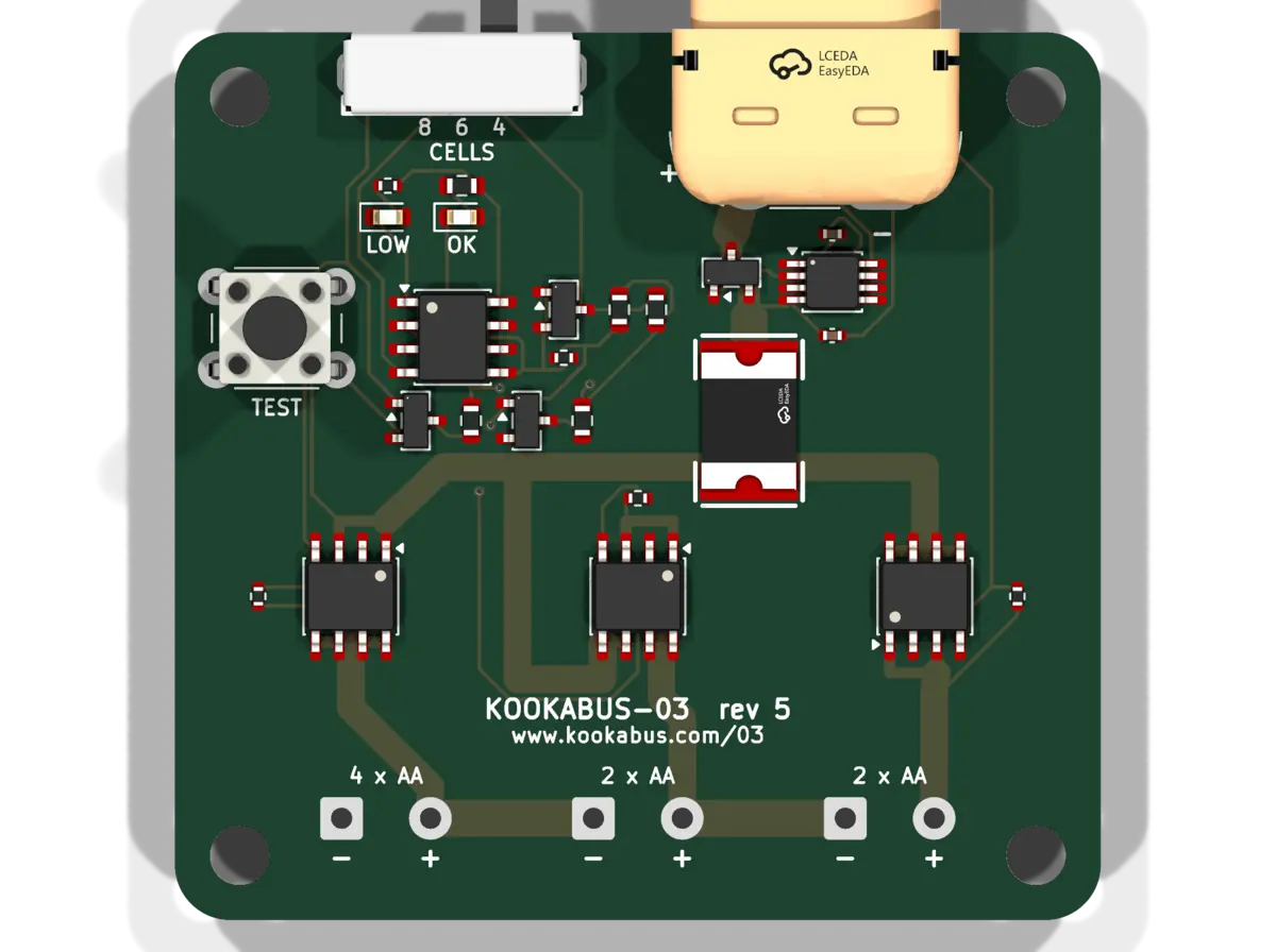
- J1
- OUT. Female XT60; its mating end overhangs the top edge so a plug's shell slides over it.
- SW1
- CELLS. Slide switch, 8 / 6 / 4, lever over the top edge.
- SW2
- TEST. A 13 mm tall button, so its plunger comes up through the enclosure lid.
- LOW, OK
- Red D9 and green D10. Lit only while TEST is held.
- F1
- 3 A hold, 5 A trip resettable fuse.
- Q26, U12
- Reverse-current block between F1 and the XT60: an AO3400A MOSFET driven by an LM74610 smart diode controller.
- Q21 to Q23
- Selector FETs for 4, 6 and 8 cells, AO4805 dual P-channel.
- J2 to J4
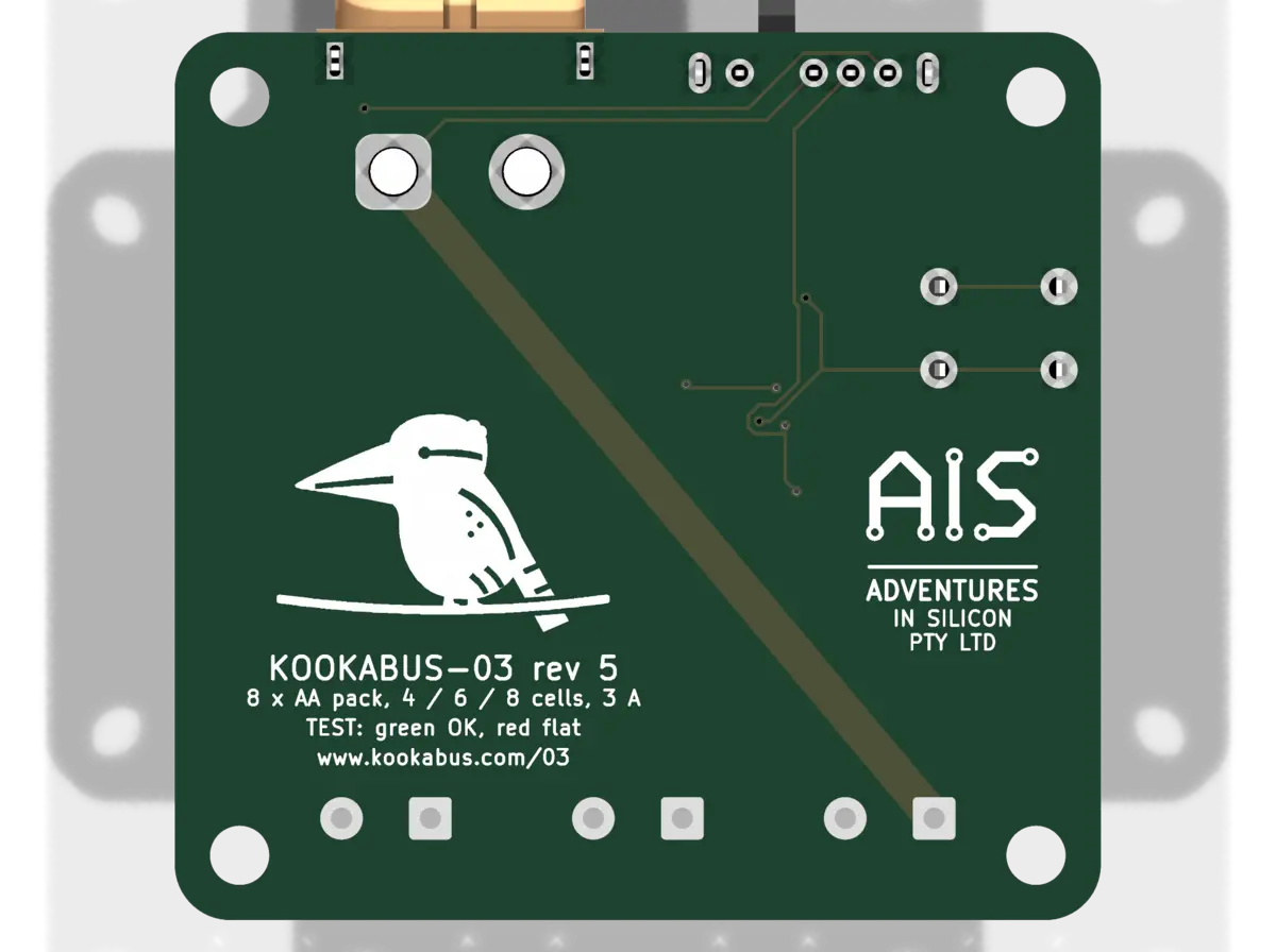
- Wire pads for the 4 × AA and two 2 × AA holders, marked − and +.
More views
Specifications
Values are calculated from the design, not measured. No hardware has been built yet.
Electrical
| Output voltage | 4, 6 or 8 cells in series, set by SW1. 4.8 / 7.2 / 9.6 V with NiMH; 6.0 / 9.0 / 12.0 V with fresh alkaline, up to 12.8 V open circuit. |
|---|---|
| Output current | 3 A hold, 5 A trip (PTC F1). AA cells sag heavily above about 2 A. |
| Output connector | XT60PW-F, female |
| TEST thresholds | Green above, red below 4.46 / 6.64 / 8.76 V in 4 / 6 / 8-cell mode: 1.12 / 1.11 / 1.09 V a cell, within about 3 %. 2 to 9 mA while held. |
| Reverse current | Blocked from the XT60 into the board, up to 30 V above the pack: at most 110 µA flows back. About 0.07 V drop at 3 A. |
| Idle drain | 6 / 10 / 13 µA with 4 / 6 / 8 cells, for the selector's gate resistor. The TEST circuit, both LEDs and the reverse-current block draw nothing while the button is released. |
| Reverse feed | With any position selected, no tap can feed another: the 6-cell FET pair is back to back, and the other two point their body diodes the safe way. |
How it works
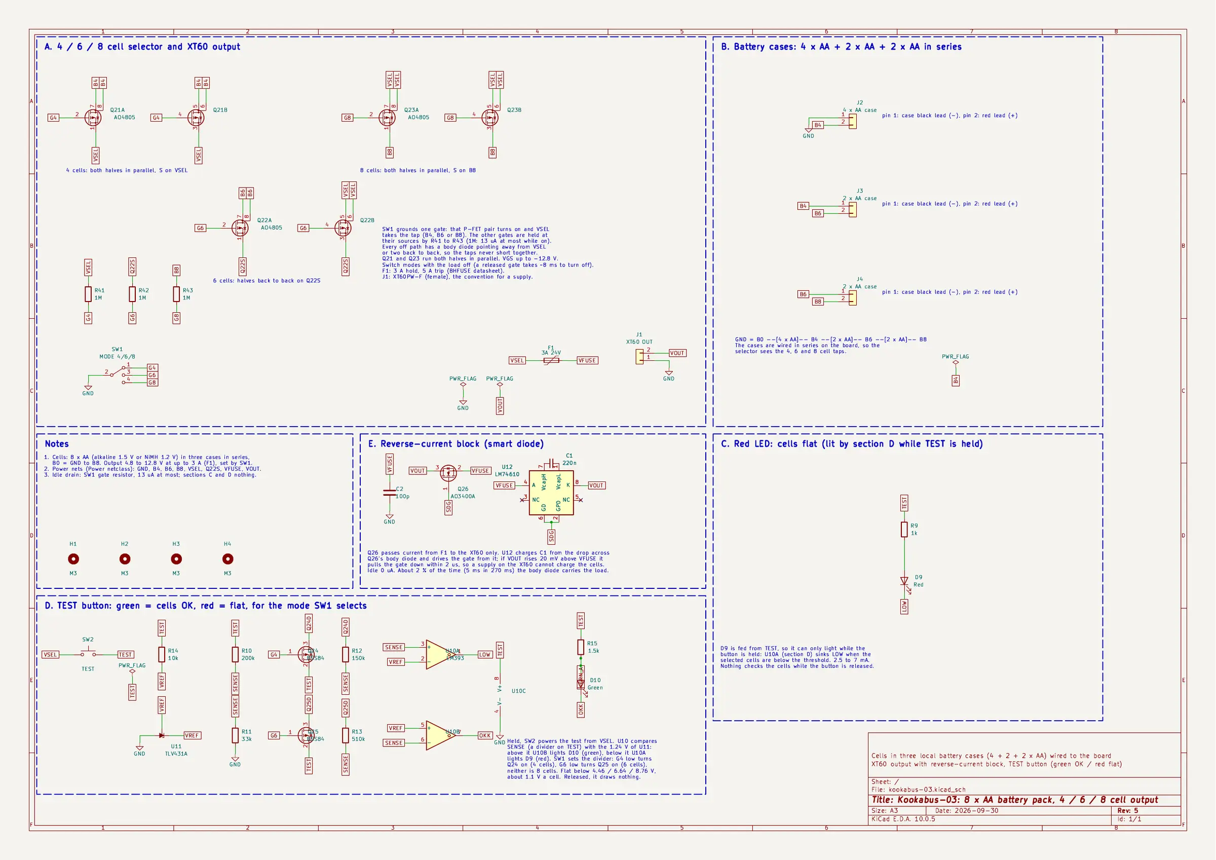
- Selector: SW1 grounds the gate of one of Q21, Q22 or Q23; 1 MΩ resistors hold the others off. The switch carries microamps, the FETs carry the load.
- TEST: the button powers an LM393 comparator and a 1.24 V TLV431 reference from the selected output. A divider scales the output to the reference, and two small FETs switch its ratio from SW1's gate lines, so the threshold follows the switch.
- Reverse-current block: Q26 sits in the output with its body diode pointing out of the board, and the LM74610 turns it on only while current flows outward. The controller has no ground pin and no idle current: it runs from a small capacitor that it recharges for about 5 ms in every 270 ms, and for those 5 ms the output is about 0.7 V lower. It also blocks the energy a braking motor returns, so the load's own capacitors or clamp must absorb that.
Main parts
| Ref | Part | Function |
|---|---|---|
| J1 | AMASS XT60PW-F | Output |
| SW1 | ROCPU SK-13D07-4, SP3T slide | 4 / 6 / 8 cell select |
| SW2 | 6 × 6 mm tactile, 13 mm tall | TEST |
| Q21–Q23 | AO4805, dual P-FET, 30 V | Cell selector |
| F1 | BHFUSE BSMD2920-300-24V | 3 A resettable fuse |
| Q26 | AO3400A, N-FET, 30 V | Reverse-current block |
| U12 | TI LM74610 | Smart diode controller for Q26 |
| U10 | LM393 | TEST comparator |
| U11 | TI TLV431A | 1.24 V reference |
| Q24, Q25 | BSS84 | TEST threshold for 4 and 6 cells |
Mechanical
| Board | 50 × 48 mm, 2 layers, 1 oz copper, 1.6 mm FR-4, all parts on the top |
|---|---|
| Mounting | Four M3 holes, 3.5 mm in from each corner |
| Top edge | SW1 lever and J1's mating end, both over the edge |
| Bottom edge | Three pairs of wire pads, 1.15 mm holes 4.8 mm apart, for leads up to 0.5 mm² |
Enclosure
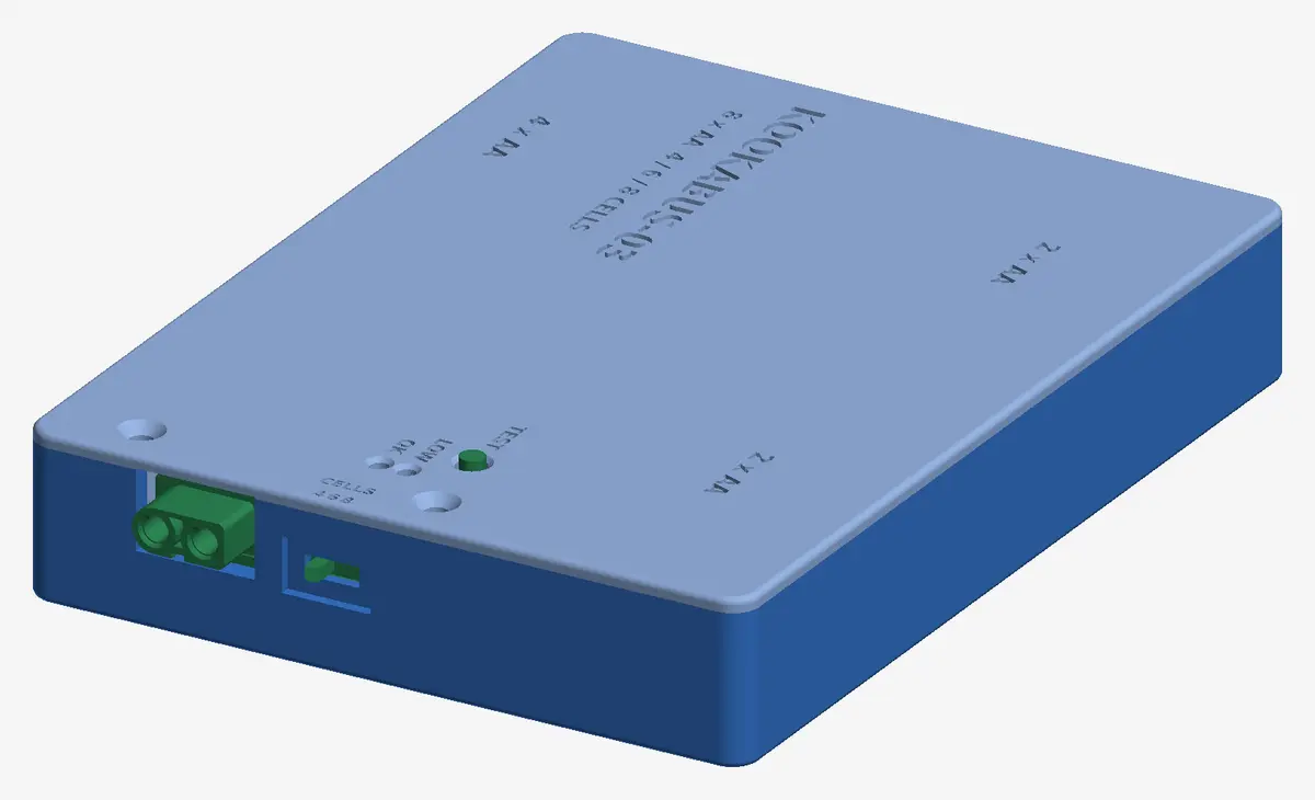
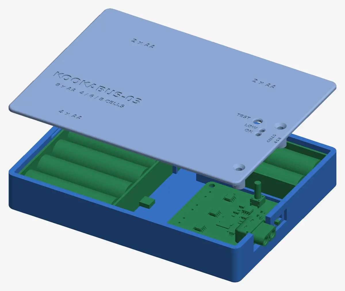
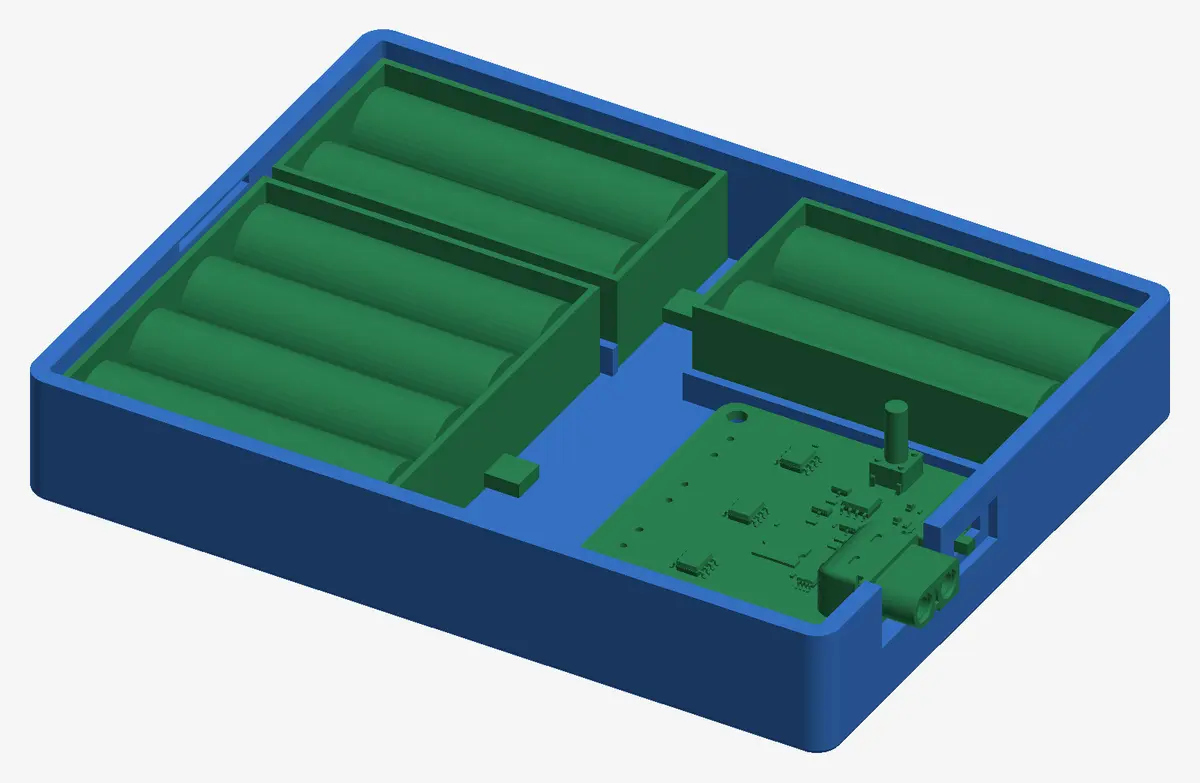
A printed box holds the board and all three battery holders. Two screws at the XT60 end open the lid to change cells; nothing else comes apart. The TEST button comes through the lid, the LOW and OK LEDs show through marked holes, and the switch and XT60 sit in windows in the end wall.
Parts
| Part | Size | File |
|---|---|---|
| Base | 139.0 × 105.5 × 21.8 mm, print floor down | kookabus-03-base.stl |
| Lid | 2 mm, print top face down | kookabus-03-lid.stl |
| DIN-rail clip, optional | 100 × 64 mm plate, TS35 rail | kookabus-03-din-clip.stl |
Closed, the box is 139.0 × 105.5 × 23.8 mm, or 32.8 mm with the DIN clip.
Battery holders
| Qty | Part | DigiKey | Price each |
|---|---|---|---|
| 1 | Keystone 2478, 4 × AA, open, 6 in leads | 36-2478-ND | US$2.08 |
| 2 | Keystone 2463, 2 × AA, open, 6 in leads | 36-2463-ND | US$1.37 |
DigiKey prices at quantity 1, checked 30 September 2026. Other holders fit if you change their sizes and hole positions at the top of the FreeCAD script and rebuild.
Hardware
| Qty | Part | Where |
|---|---|---|
| 4 | M3 heat-set insert, 4.6 mm knurl, 5 mm long | Board posts |
| 2 | M3 × 20 countersunk | Lid, through the board into the inserts |
| 2 | M3 × 6 pan head | Board, the two holes away from the XT60 |
| 6 | M2.5 × 5 countersunk and M2.5 nut | Battery holders, nuts in pockets under the floor |
| 4 | M3 × 6 countersunk and M3 nut | DIN clip, optional; fit it before the holders |
Assembly
- Press the four heat-set inserts into the board posts.
- Fit the DIN clip, if you want one, with four M3 screws down through the floor. The holders cover the screw heads.
- Screw the holders down through their own holes, lead ends toward the channel beside the board.
- Cut the leads to length and solder them to the wire pads, black to − and red to +: 4 × AA to J2, the 2 × AA holders to J3 and J4. Check each holder's polarity with a meter before fitting cells; a reversed holder is not protected.
- Mount the board on its posts, XT60 and switch in the end wall, with two M3 × 6 screws in the holes away from the XT60.
- Fit the cells and the lid: hook its tab under the far wall, lower it over the TEST button and fit the two M3 × 20 screws at the XT60 end.
Downloads
Documents
Board design
- KiCad 10 project, Gerbers, BOM, placementNot yet published