Kookabus

I²C boards for machines that run on real batteries.

Hot-swap power, servo drive and sensing on one 4-pin bus. Works with Qwiic and PiicoDev. Designed in Australia.

The boards

Each board fixes one problem that turns up when a machine runs on batteries. Each has its own site with the full technical detail: specifications, connectors, addresses and code.

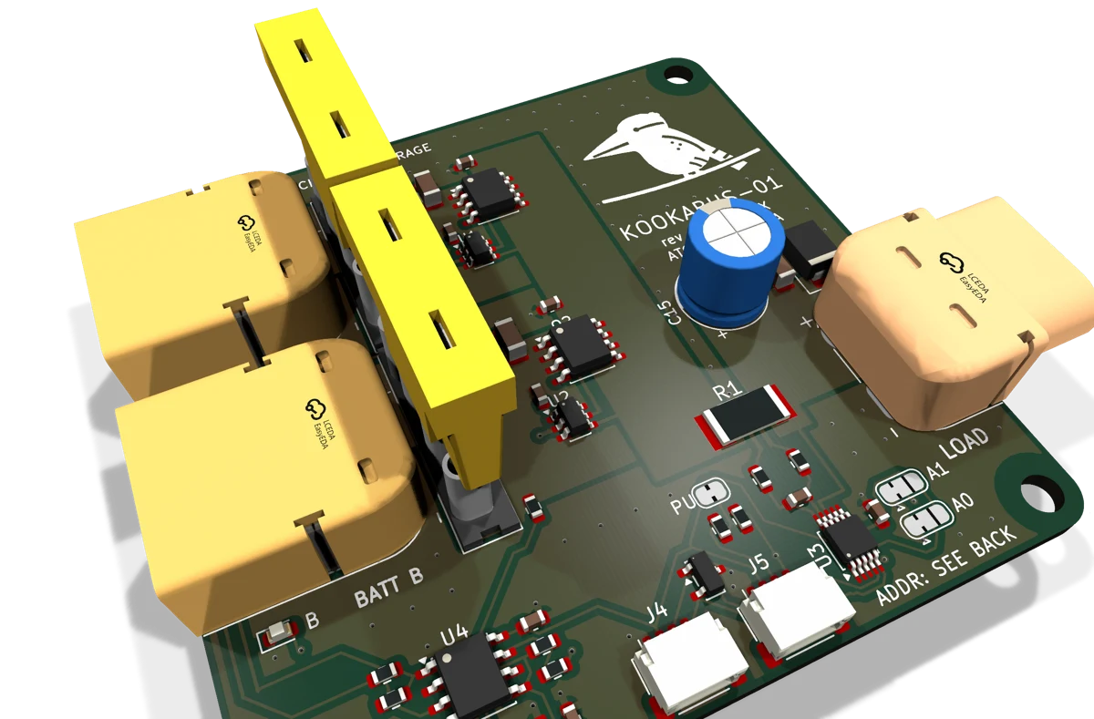
Kookabus-01

Dual 5S hot-swap battery board

Available 25 October 2026AUD $59

The problemChanging the battery switches the robot off, and the first sign of a flat pack is a machine that has stopped.

Two 5S packs in, one load out, 100 W peak. Pull a pack and the load never notices. Bus voltage, current and power come back over I²C from an INA226, so your code knows when it is time to swap.

Open the Kookabus-01 site
Kookabus-02

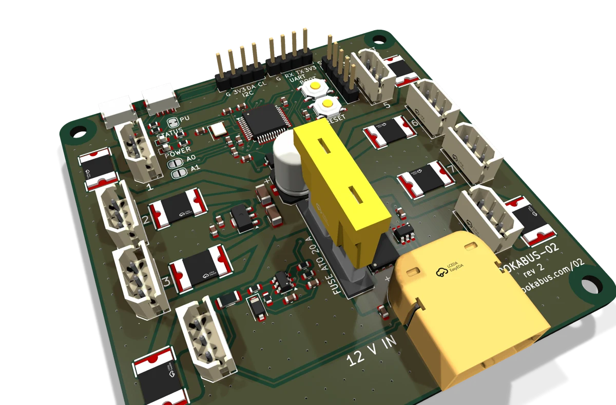
Eight-port serial bus servo driver

Coming 1 November 2026

The problemBus servos need a fast half-duplex serial line that ties up a UART, and on a shared power lead one stalled servo can take the rest down with it.

Drives up to eight ST3215 or other Feetech-protocol bus servos from the same I²C connector. One 12 V XT60 input, a 20 A fuse, and a resettable fuse on every port so one stalled servo never takes down the rest.

Open the Kookabus-02 site
Kookabus-03

Eight-cell AA battery pack

Rev 5, in design

The problemA small robot needs 6 to 12 V. A lithium pack needs a charger and care; a bare AA holder has loose wires, no fuse and no way to tell if the cells are flat.

Eight shop AA cells, alkaline or NiMH, switched to 4, 6 or 8 in series and out through an XT60 behind a 3 A resettable fuse. The output blocks reverse current, and a TEST button shows green or red for the cells in use.

Open the Kookabus-03 site

One connector across the family

Kookabus-01 and Kookabus-02 each carry two 4-pin bus connectors, so boards chain from one to the next and back to your controller. Kookabus-03 is a plain power source with no bus connection.

YOUR CONTROLLER Pi, Pico, Arduino KOOKABUS-01 0x40 to 0x45 KOOKABUS-02 0x14 to 0x17 GND 3V3 SDA SCL

The connector is the 4-pin JST-SH 1.0 mm used by PiicoDev and Qwiic, with the same pin order, so the boards plug straight into those ecosystems and their cables.

Signals
GND, 3.3 V, SDA, SCL. Logic is 3.3 V.
Chaining
Two connectors per board. Cable in on one, out to the next on the other.
Addressing
Solder jumpers A0 and A1 on each board select its I²C address, so up to four of the same board share a bus. Kookabus-01 uses 0x40 to 0x45 and Kookabus-02 uses 0x14 to 0x17, so the two never clash.
Pull-ups
Boards ship with 4.7 kΩ pull-ups on. Cut the PU jumper on all but one board per bus, or on all of them if the host has its own.