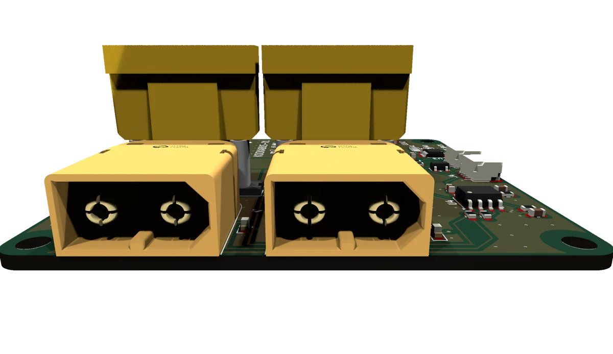
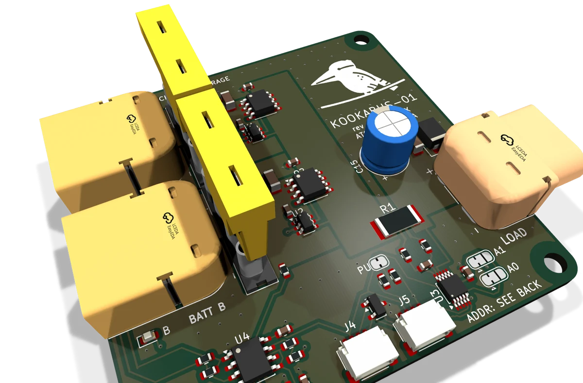
The problem it solves
A battery-powered robot stops when its pack runs flat, and changing the pack means switching everything off: the computer reboots and the job starts again. Most packs give no warning either, so the first sign of a flat battery is a machine that has stopped.
Kookabus-01 takes two packs at once. Unplug the empty one and the other carries the load with no brownout. The board reports voltage, current and power over I²C, so your code can ask for a swap before the pack runs out.
- Packs
- 2 × 5S lithium-ion on XT606S maximum, 12 to 25.2 V per input
- Output
- 1 × XT60, 100 W peak40 W continuous, 2.7 A typical
- Fuses
- 2 × 10 A ATO bladeShip separately, fit before use
- Swap
- Ideal-diode ORing, no brownout20 mV drop, reverse-polarity tolerant
- Monitor
- INA226: volts, amps, watts1.25 mV and 0.5 mA per bit
- I²C
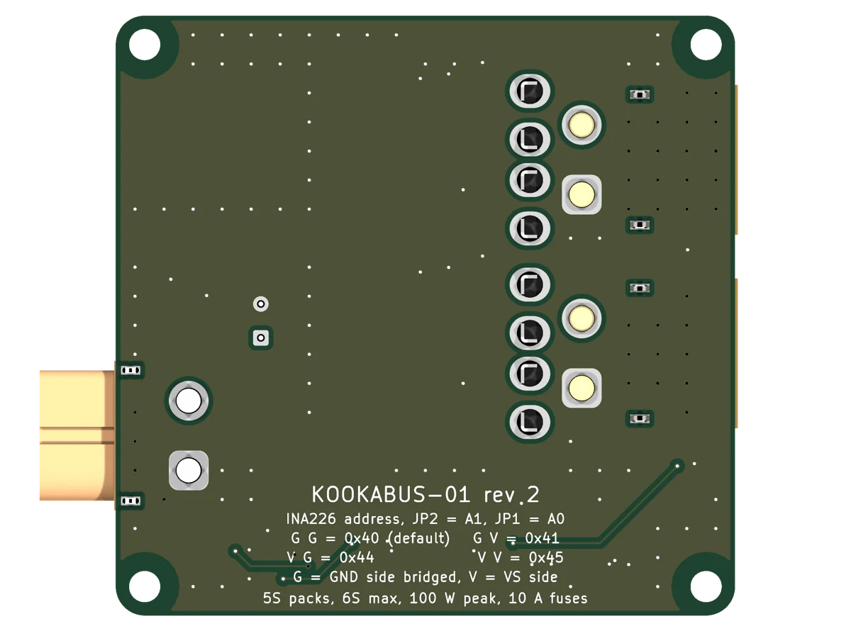
- 0x40 default, 0x41, 0x44, 0x45Qwiic and PiicoDev, 3.3 V from the host
- Size
- 64 × 62 mm, four M3 holesPrintable enclosure with DIN-rail clip
- Status
- Rev 2, AUD $59Available 25 October 2026
What it does
Kookabus-01 joins two lithium-ion packs into one uninterrupted supply for a robot or other mobile load. Each pack feeds an ideal-diode stage, so the higher-voltage pack carries the load and a pack can be unplugged and replaced while the other keeps the bus up. A high-side sensor on the output reports bus voltage, current and power over I²C, and an LED beside each battery connector shows which pack is supplying the load.
The board is a power pass-through. It does not regulate, charge or balance, and it needs no configuration to swap packs. Only the sensor and LEDs need the host's 3.3 V.
- Hot-swappable battery supply for ROS 2 and other mobile robots.
- Battery monitoring for Raspberry Pi, Jetson and microcontroller hosts.
- Bench supplies from cordless-tool packs such as Ryobi ONE+ and Einhell Power X-Change on XT60 adapter leads.
Find what you need
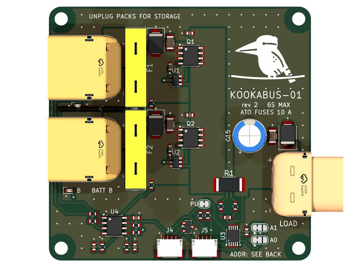
The board
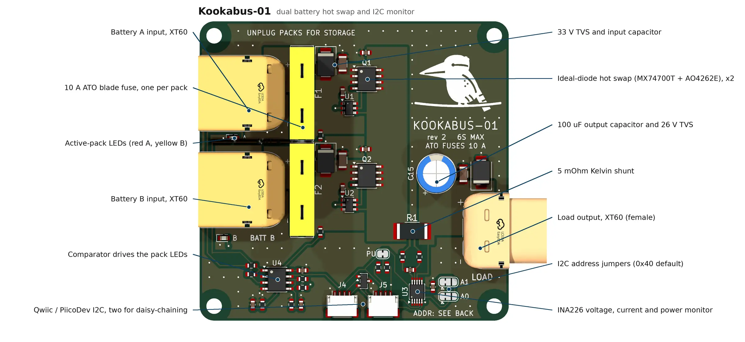
- J1, J2
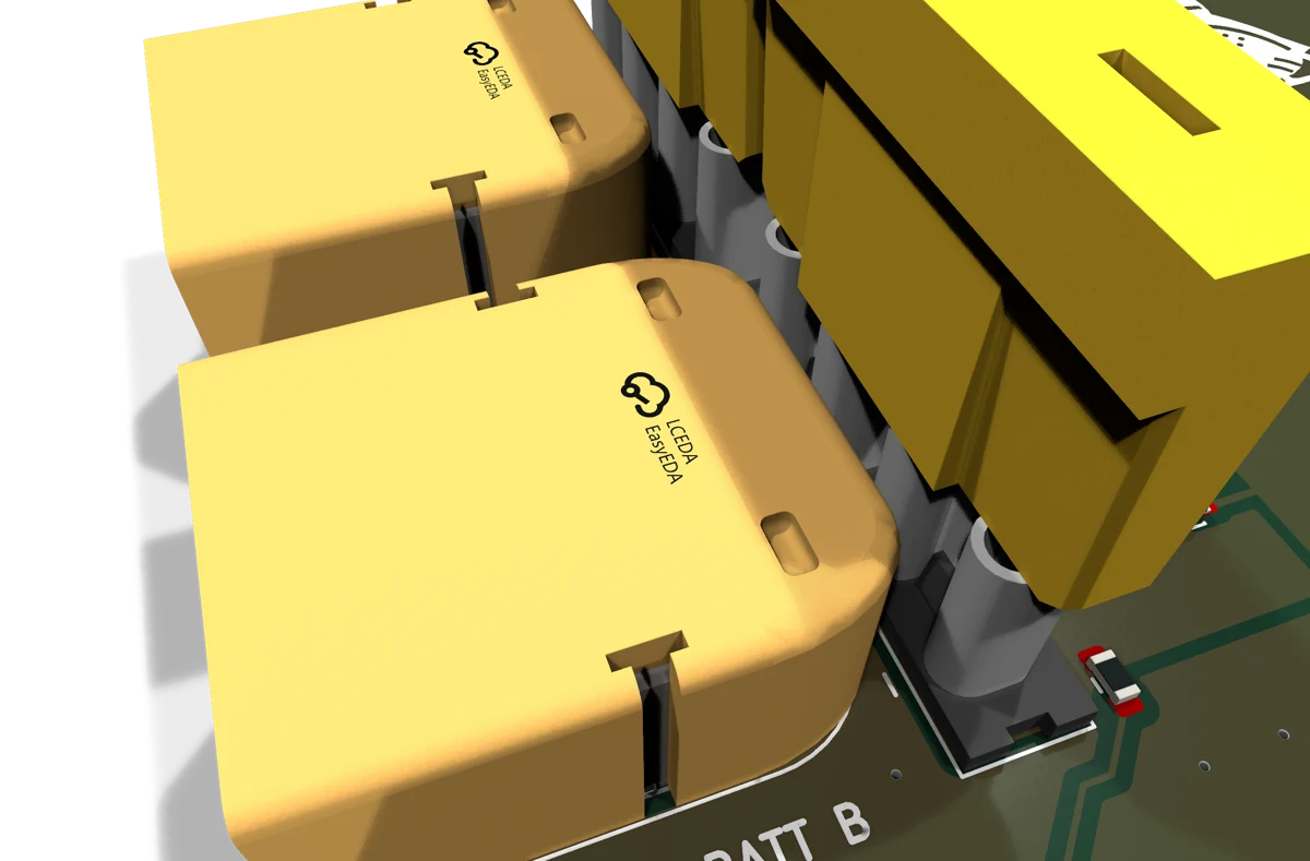
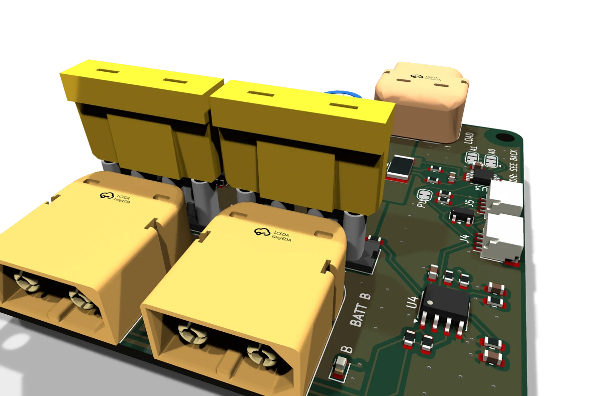
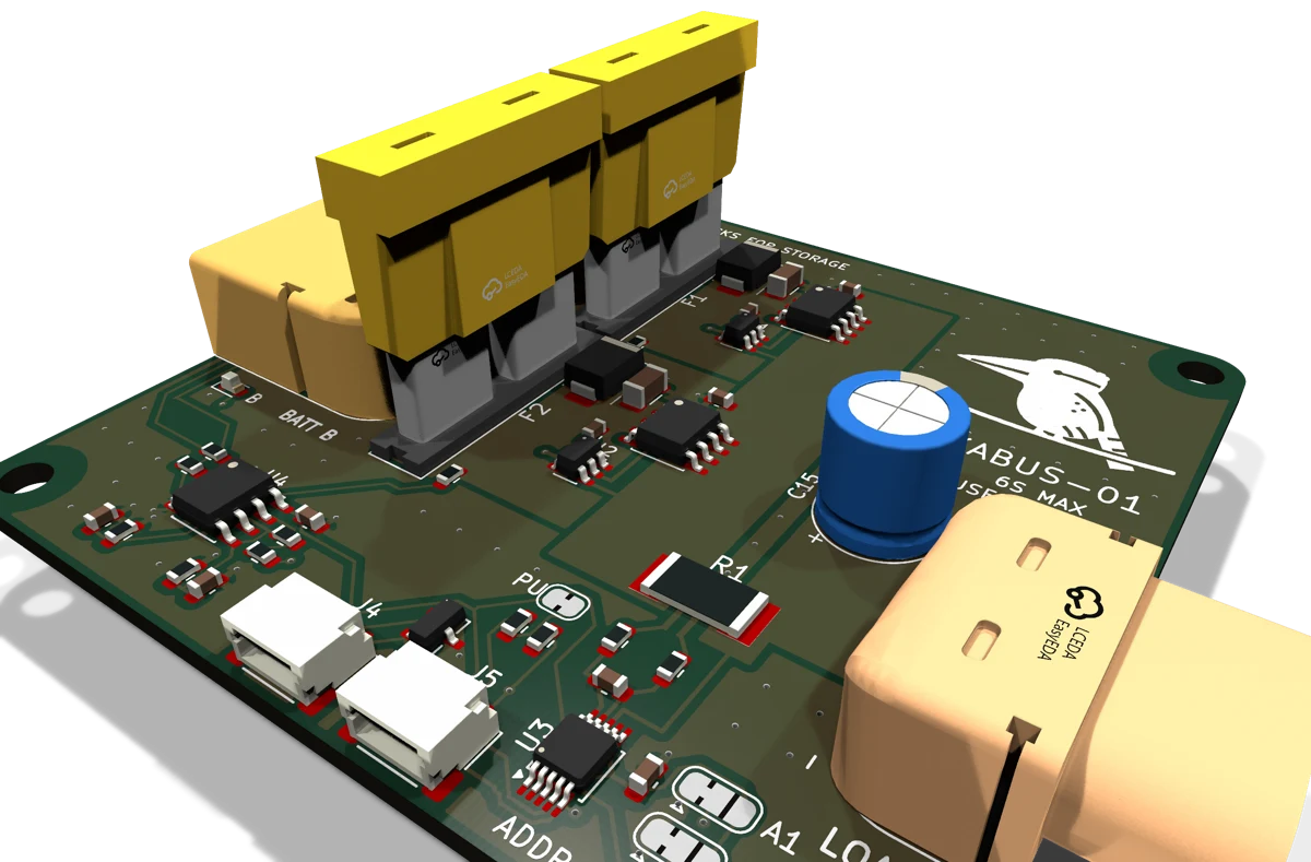
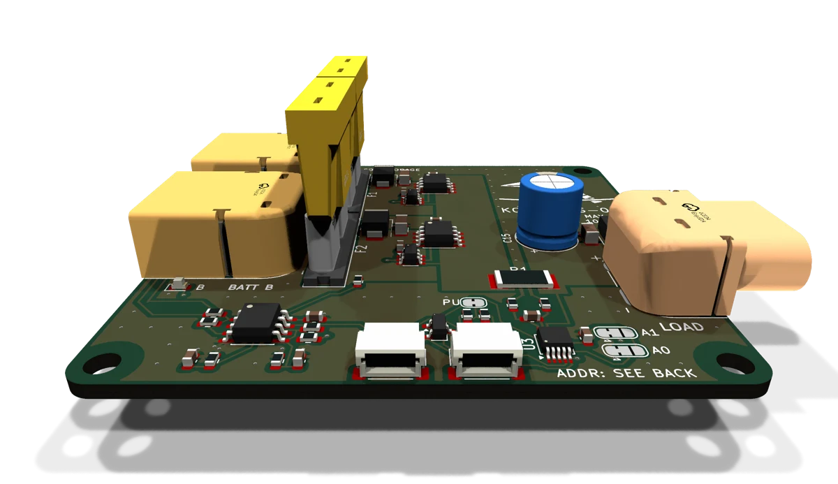
- BATT A and BATT B. Male XT60 pack inputs.
- J3
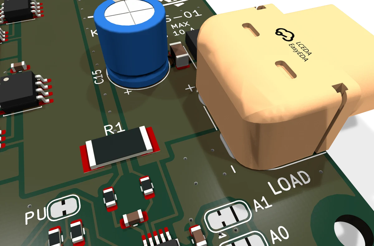
- LOAD. Female XT60 output, nose overhangs the right edge.
- F1, F2
- ATO blade fuse holder for each pack. Fit 10 A fuses before use.
- U1 Q1, U2 Q2
- Ideal-diode stage for each pack: MAX74700T controller and AO4262E 60 V FET.
- C15
- 100 µF output capacitor on VLOAD, in parallel with 4.7 µF ceramic.
- R1
- 5 mΩ 2512 shunt, Kelvin sensed.
- U3
- INA226 voltage, current and power monitor.
- U4
- MCP6002 comparator driving the two active-pack LEDs.
- LED A, LED B
- Red beside BATT A, yellow beside BATT B. The lit one is supplying the load.
- J4, J5
- JST SH 4-way I²C connectors, wired in parallel.
- A0, A1
- JP1 and JP2, INA226 address jumpers.
- PU
- JP3, cut to remove the 4.7 kΩ pull-ups.
More views