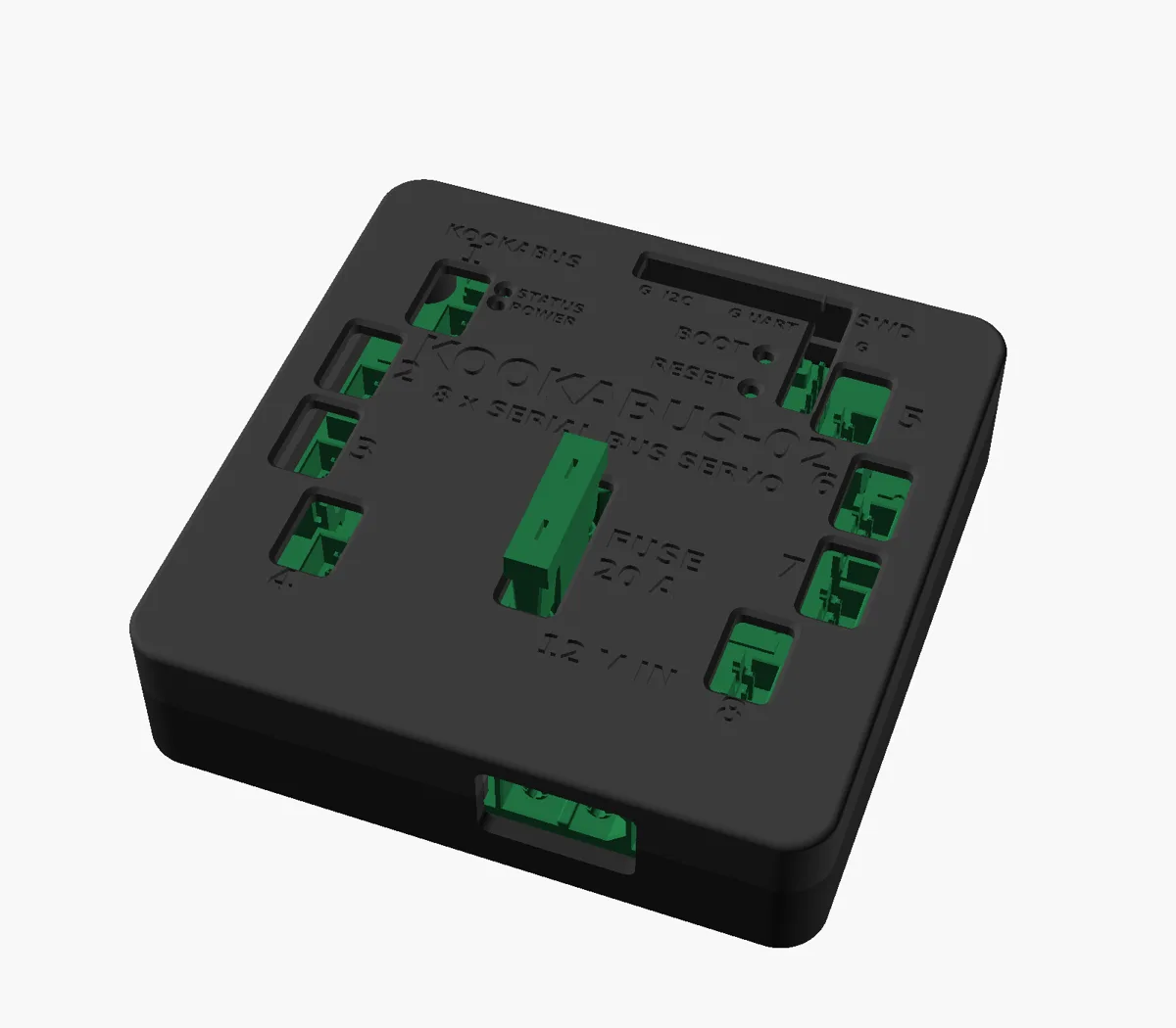
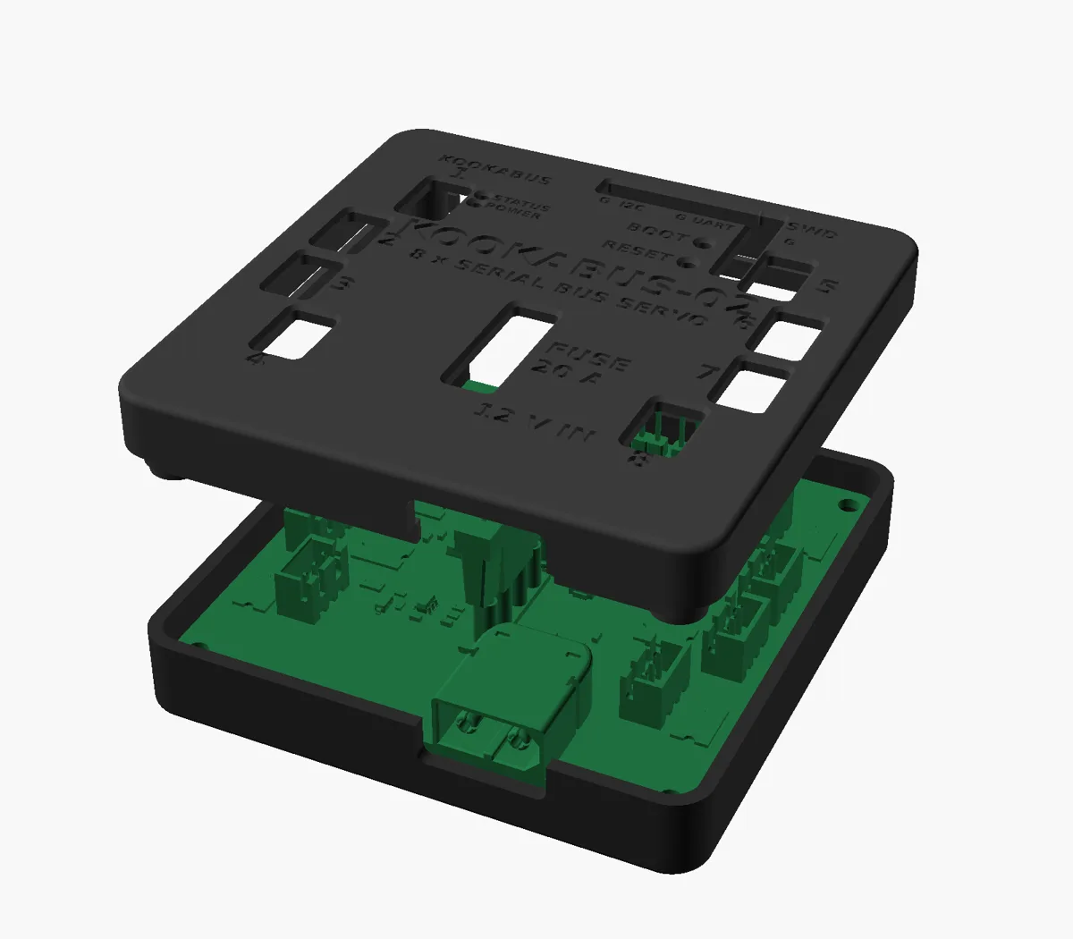
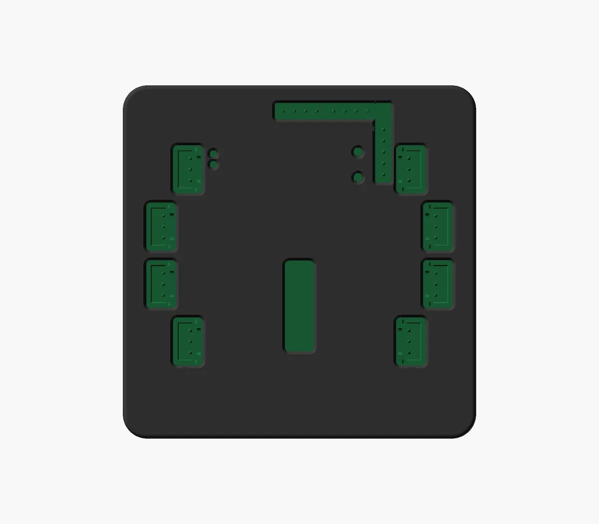
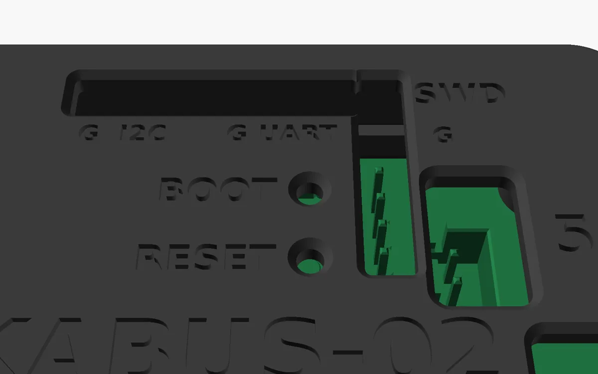
The eight servo ports, the I²C, UART and SWD headers and the 20 A fuse open through the lid, so servos plug in and the fuse can be swapped with the case closed. The lid is labelled with the board name, the port numbers and each header, and has windows for the POWER and STATUS LEDs and pinholes for BOOT and RESET. The two Kookabus connectors and the XT60 pass through cut-outs in the side walls.
Parts
| Part | Footprint | File |
|---|---|---|
| Base | 80 × 80 × 12 mm | kookabus-02-base.stl |
| Lid | 80 × 80 × 13 mm | kookabus-02-lid.stl |
| DIN-rail clip, optional | 76 × 76 × 9 mm, TS35 rail | kookabus-02-din-clip.stl |
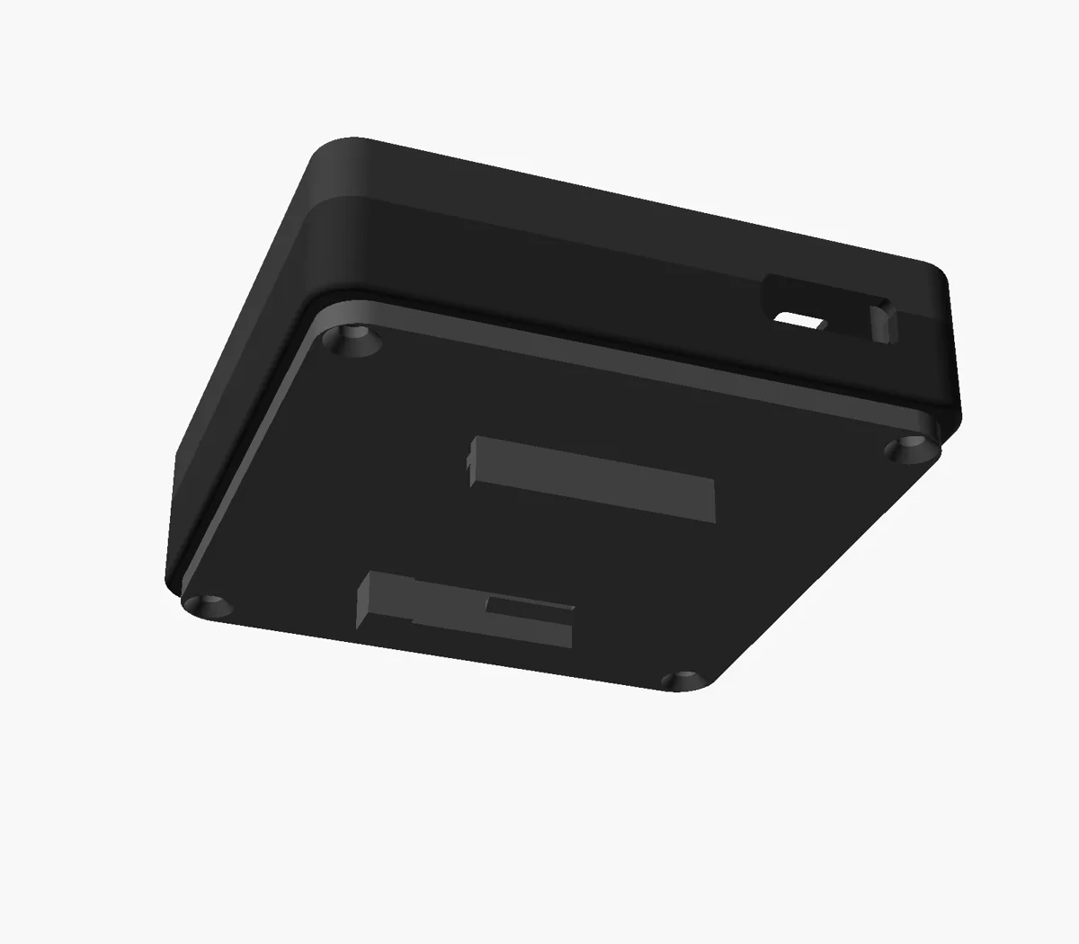
| Hardware | 4 × M3 heat-set inserts in the lid, and 4 × M3 × 12 countersunk screws up through the base. Use M3 × 16 when the DIN clip is fitted. | |
Footprints are the bounding boxes of the STL files. The case splits through the middle of the edge connector windows, so the board drops straight into the base and the base and lid print without supports.
Files
- All enclosure files zipDownload
- Assembly STEP, for CADDownload
- FreeCAD source FCStd, for editsDownload
Board dimensions, hole pattern and connector positions for a case of your own are in the mechanical section of the specifications.